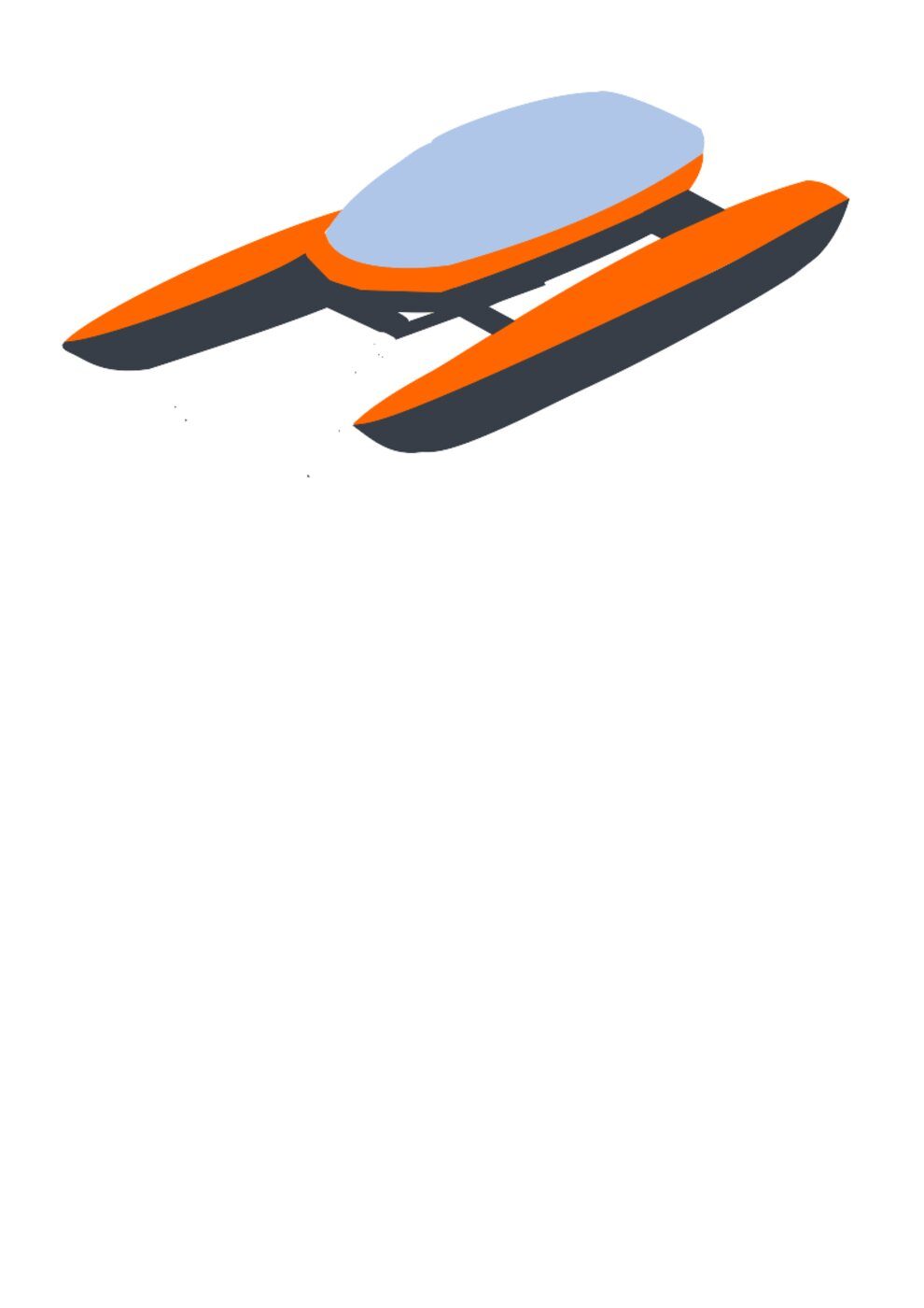
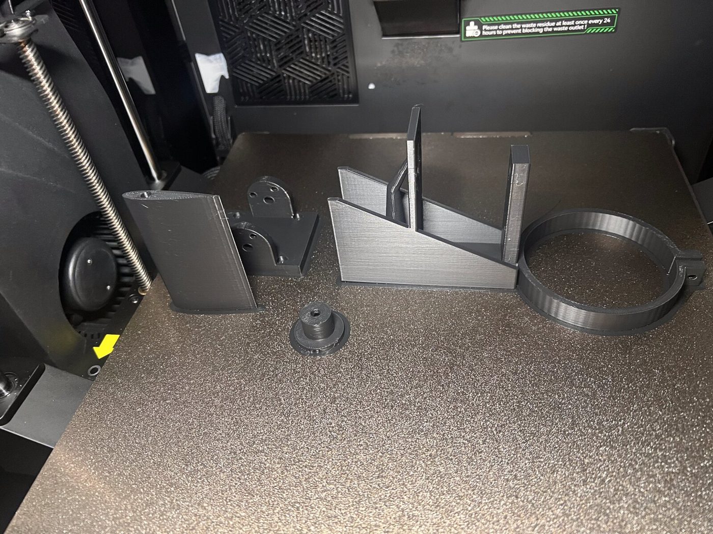
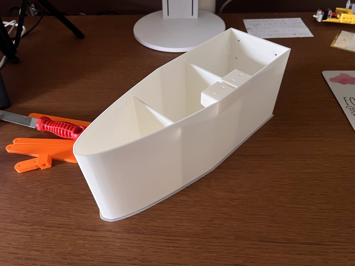
Power box printed
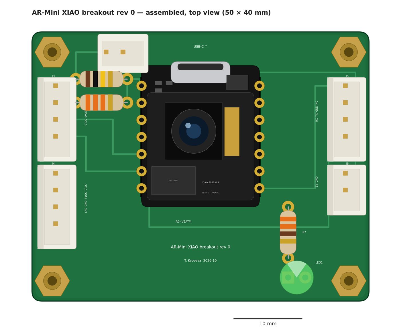
152 × 135 × 66 mm, CAD v1.7. The rev 0 breakout board is drawn.
What was tried, what broke, what changed. Newest first, real dates. Entries come from the nightly log in the repository.
Pancharevo, rain and fog. The robot packed on the back seat at 07:38 with the box of boards on the beams; at the weir on the Iskar by 08:36, the launch spot a calm pool beside it. At 08:49 the first run on open water: held at the surface, set free, driven from the phone with one thruster and the rudder. It drove off, turned and came back to the bank, floating level in the rain. The camera on the arch recorded the whole trip from the car to the water, 11,764 frames. Mission done.
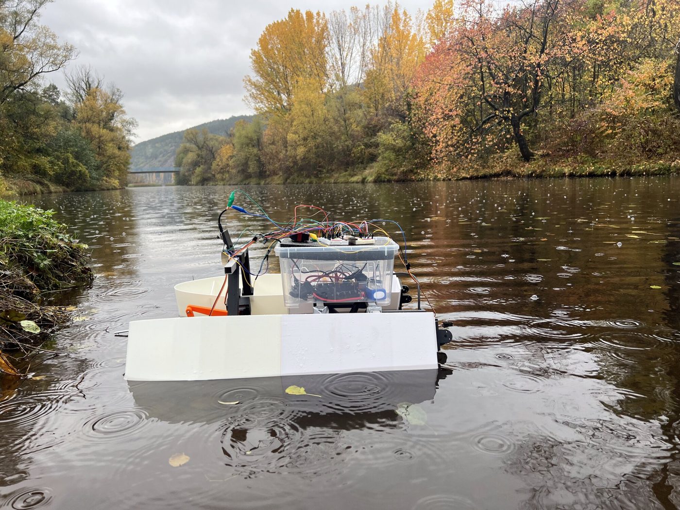
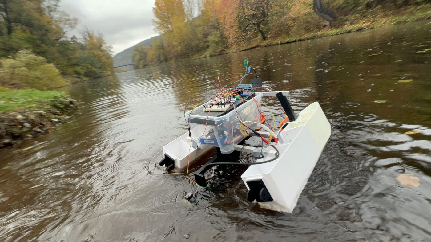
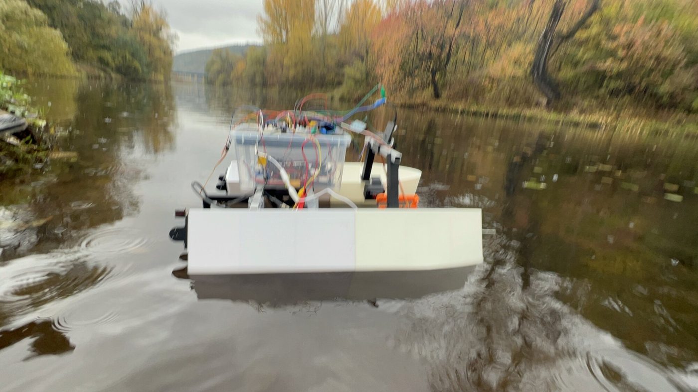
At 05:54 the 3S LiPo went on the charger inside a safety bag: balance charge at 2.2 A, full at 12.60 V after 34 minutes, 1212 mAh put back, all three cells at 4.20 V. Then the bench wiring was rebuilt from the breadboard into the final layout for the box: two boards with the controller across them, a 74HCT125 level shifter, the kill/run rocker, the battery through a 30 A inline fuse, the main switch and the fuse block, a buck for the 5 V; the divider resistor checked at 30.19 kΩ before it went in. By 11:30 the box sat across the beams with the breadboards on foam in its lid. The phone page after the first flash of the pool firmware: 12.91 V on the battery, link 187 ms; thruster, turn and one lift servo not yet working. At 14:04 the first run on battery: the thruster spun after one wire moved by a column. In the afternoon only one cradle servo followed the lift slider, still being chased. At 17:47 the robot went across a clear storage box of water: thruster nozzle and rudder blade under water, the servo above the waterline, and with the rocker on run the phone sliders drove thruster and rudder in the water.
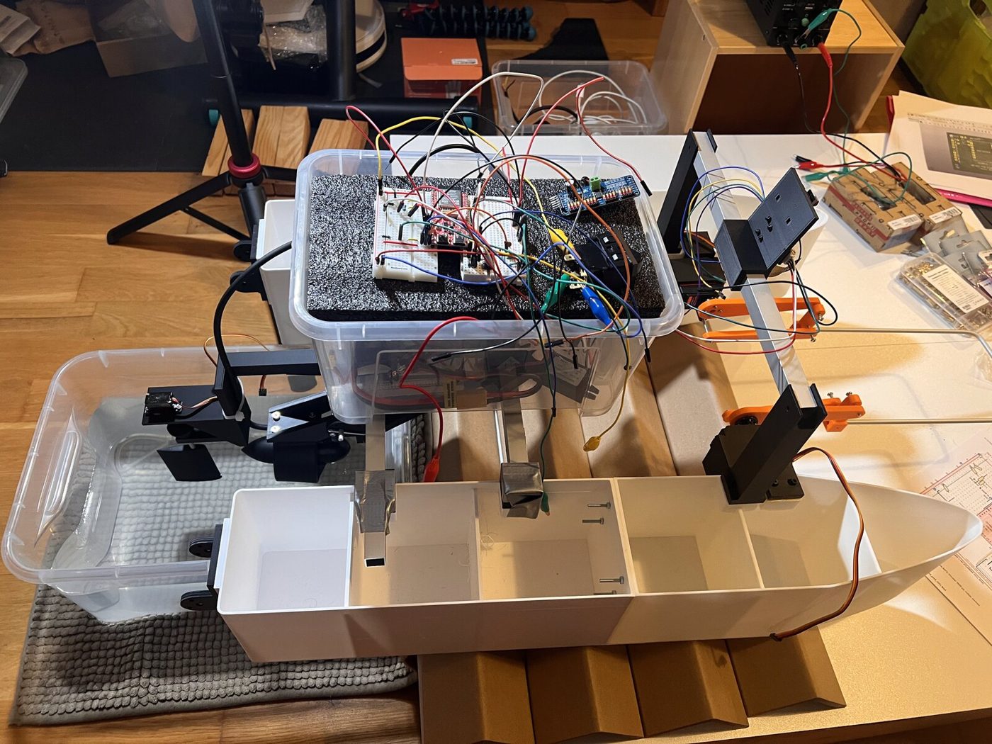
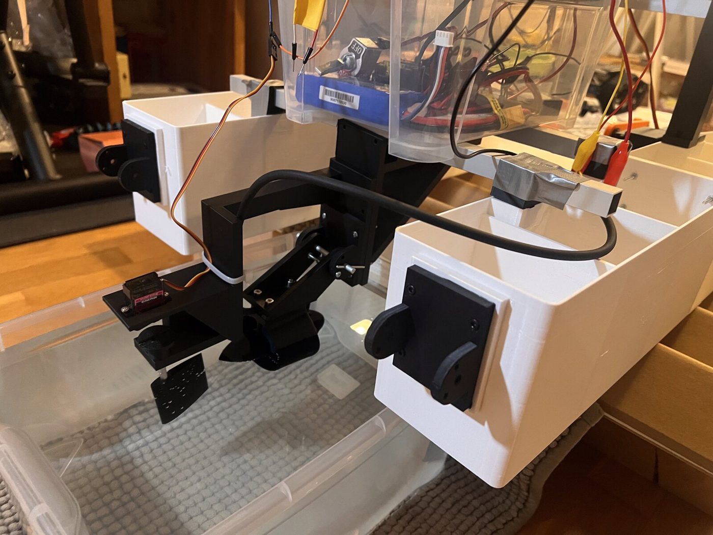
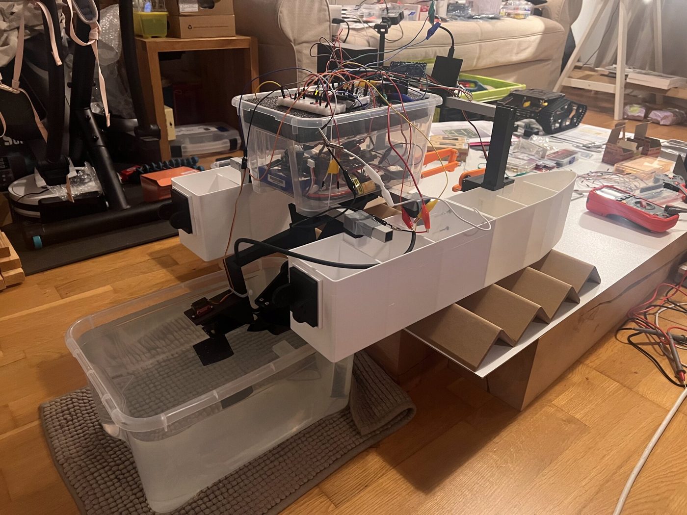
The rudder frame came off the printer at 06:18, 2 h 27 min and 104 g: a plate between the beam leg pad and the thruster bracket, a boom over the thruster, a post with the bearing and the servo seat. The Ø5 stock drilled in the vice; by 11:44 leg, frame, bracket, thruster, servo and blade were assembled on the table. By the afternoon the whole robot stood with the food box on the beams and the tracked chassis off.
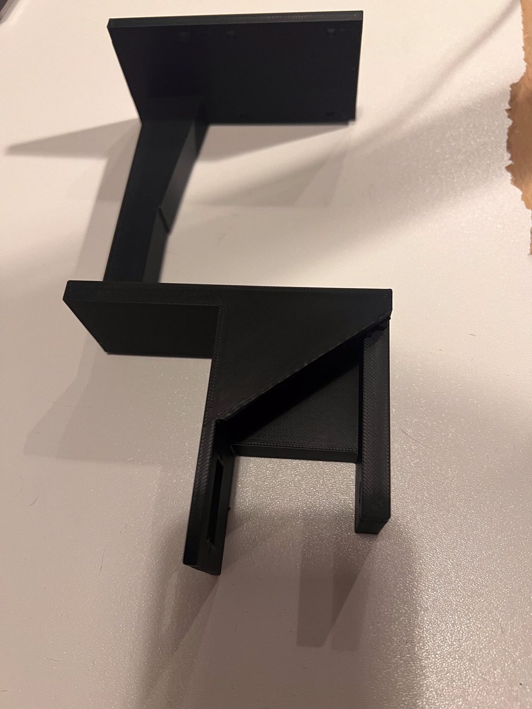
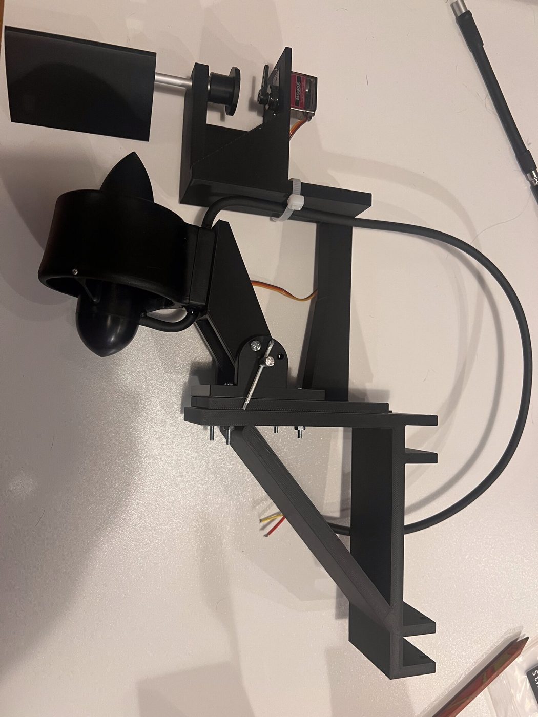
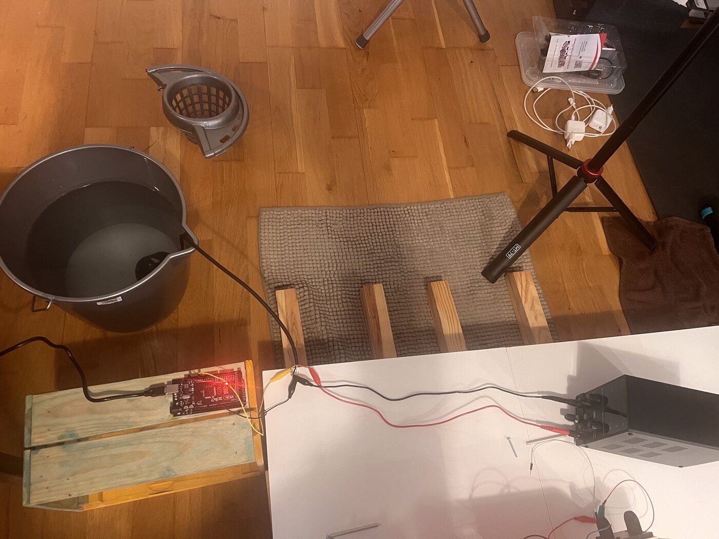
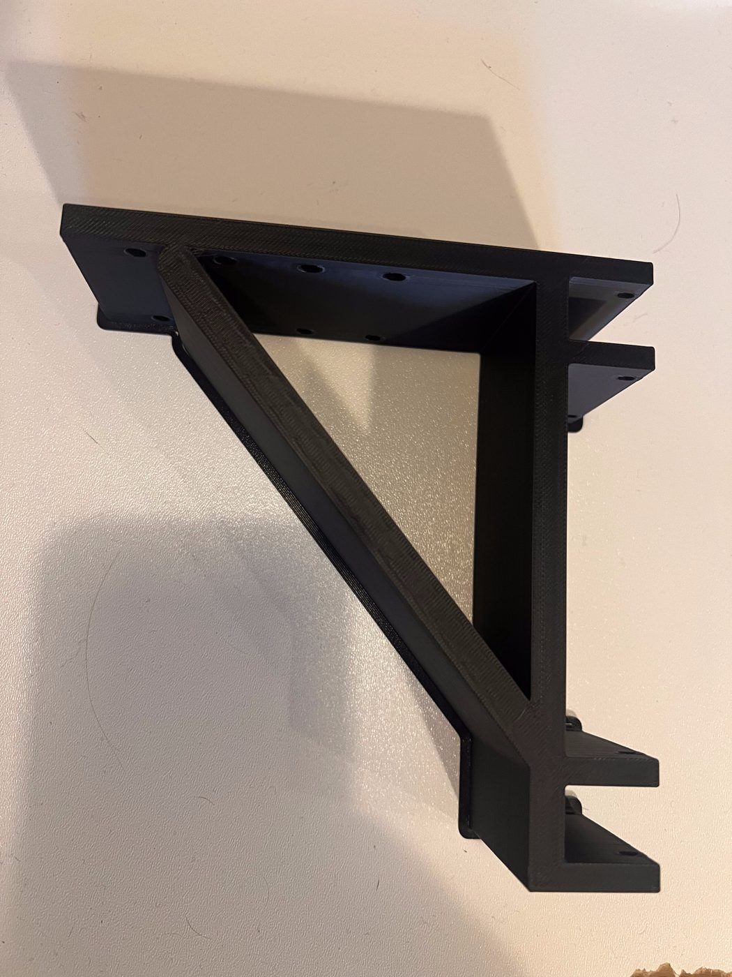
To settle whether the fault was in the controller or in the thruster, both thrusters ran from an Arduino Mega on a plain servo signal, in the bucket at 12 V. Left: 0.217 A at 1600 µs, 0.570 A at 1650, 0.202 A in reverse, all within 5 % of the numbers from the controller. Right: no spin, a click every 0.9 s, the supply pulsing into its current limit at 1.1–2.1 A and sagging to 8.75 V. The fault is in the right thruster. So the pool run gets one thruster on the centreline: a beam leg that hangs the working thruster from the two beams, with the tracked chassis off and the electronics and battery in a food box on the beams. The leg printed in black PETG on its side, no supports, 2 h 37 min and 123 g. Then a rudder, for steering with one thruster: a collar on the duct, a NACA 0015 blade and a small MG90S servo, 3 h 09 min and 103 g. The collar would not go onto the duct, so a one-piece rudder frame without the collar was drawn and printed overnight.
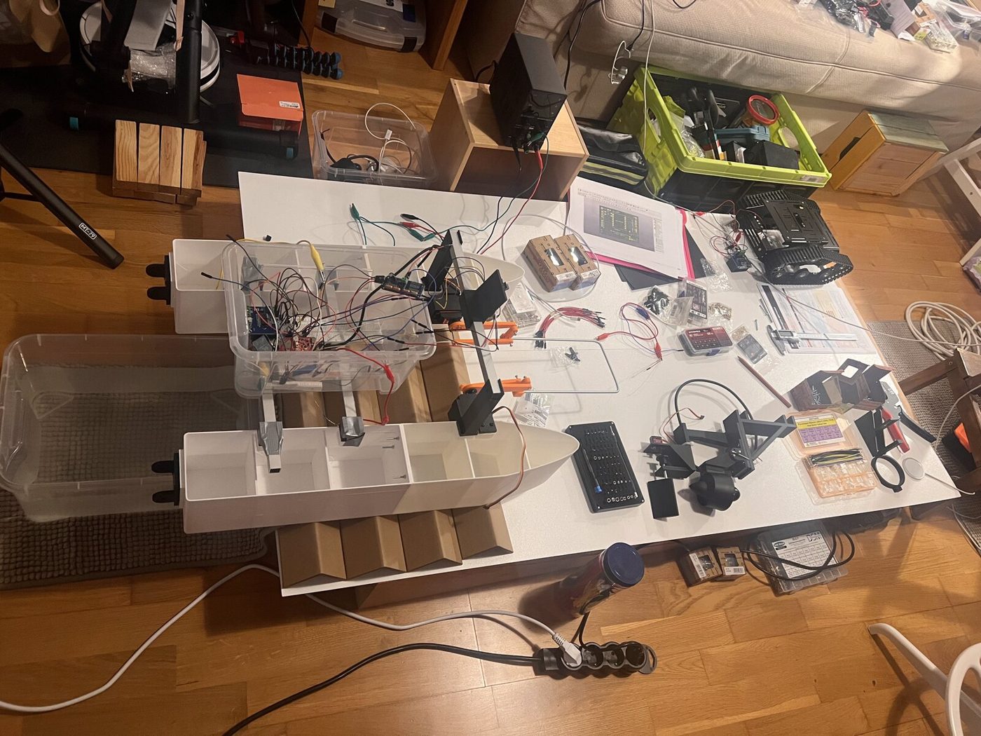
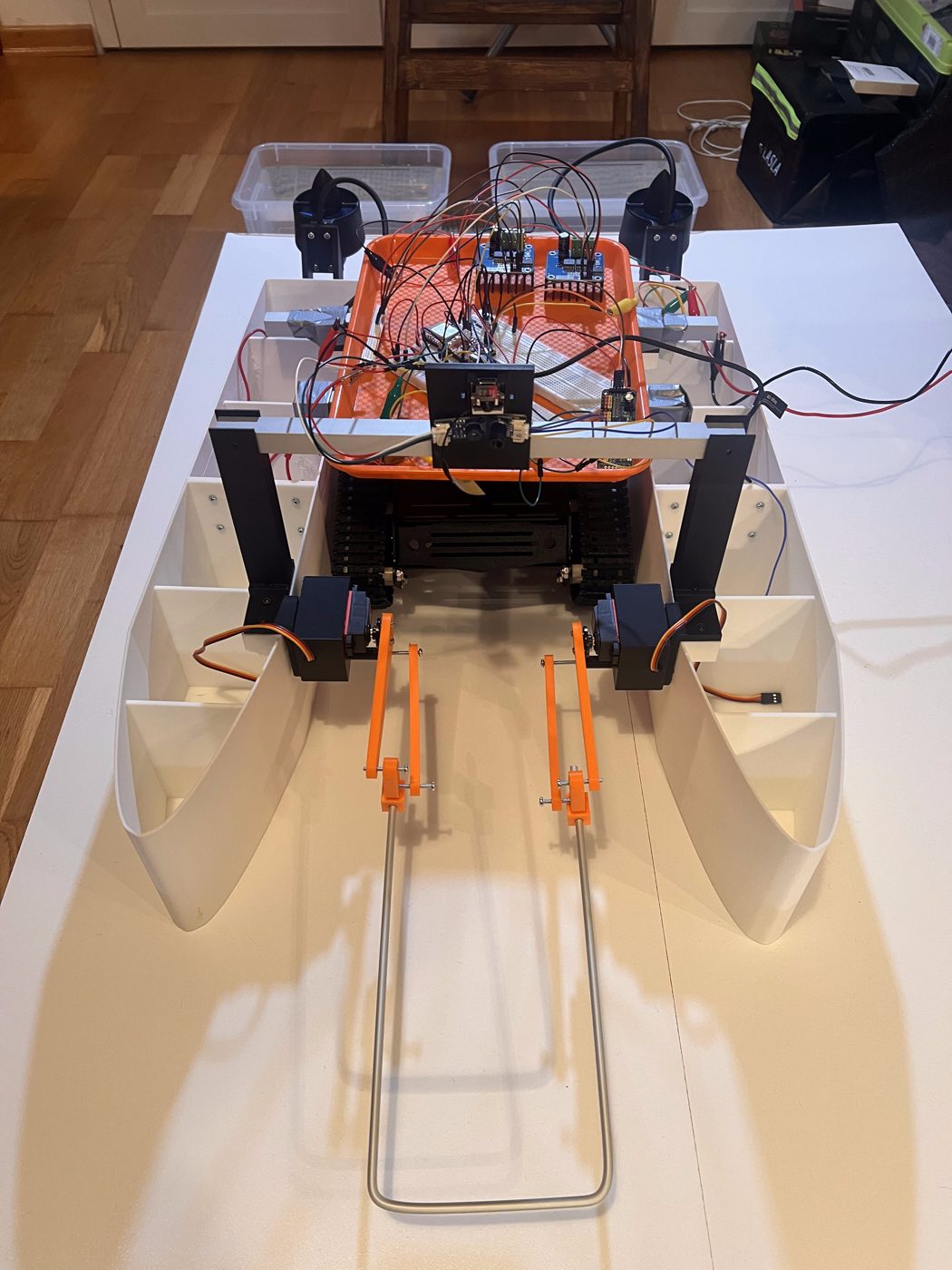
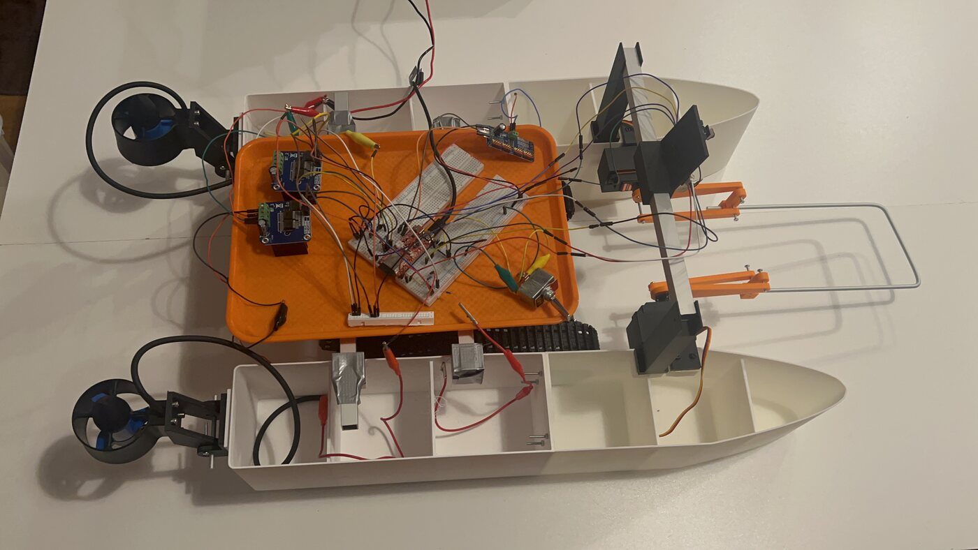
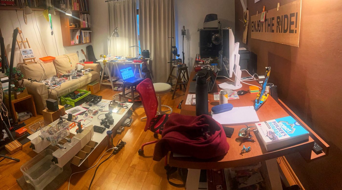
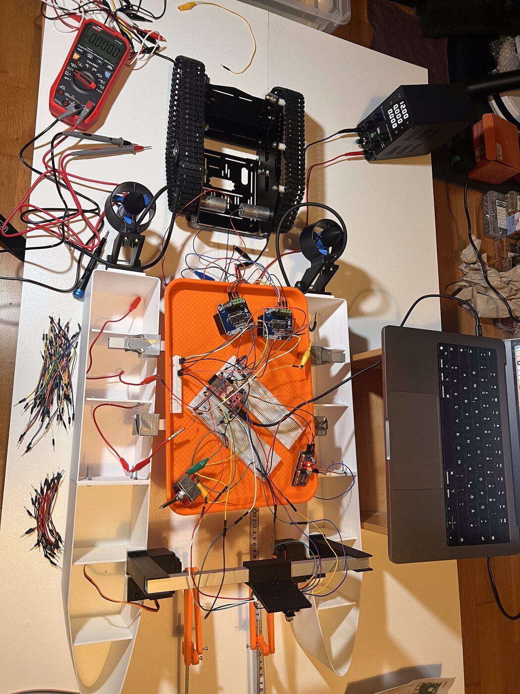
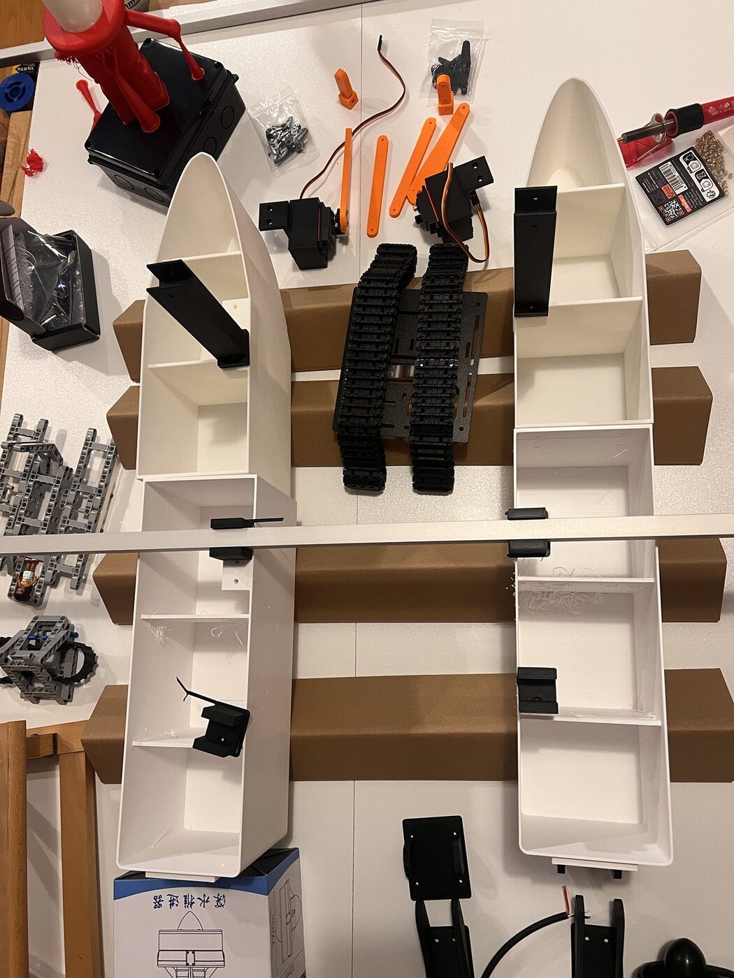
At 05:49 the first dry assembly of the whole robot: four hull sections, the four beam brackets with the aluminium beams, the tracked chassis between the hulls, the orange electronics tray with the controller, both motor drivers, the servo driver and the kill toggle, the arch with the camera head, both cradle servos with the orange linkages and the aluminium U, and both thrusters on their kick-up mounts at the transom. Nothing measured, nothing powered: a record of the first time everything sits together. Still open: the tray has no mount yet and rests on a book, the kill toggle is still on clip leads, and the right thruster is the faulty one. Also the first photographs of the lab itself, from the doorway.
The right track motor went onto the bench with the second BTS7960 driver, eight new wires on the breadboard. Before the first command the kill input kept dropping low in bursts: the toggle was still on clip leads, and a photo of the bench was what found the loose contact.
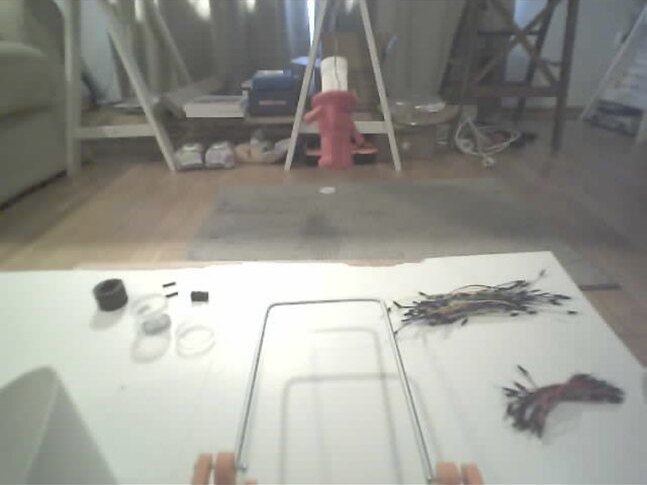
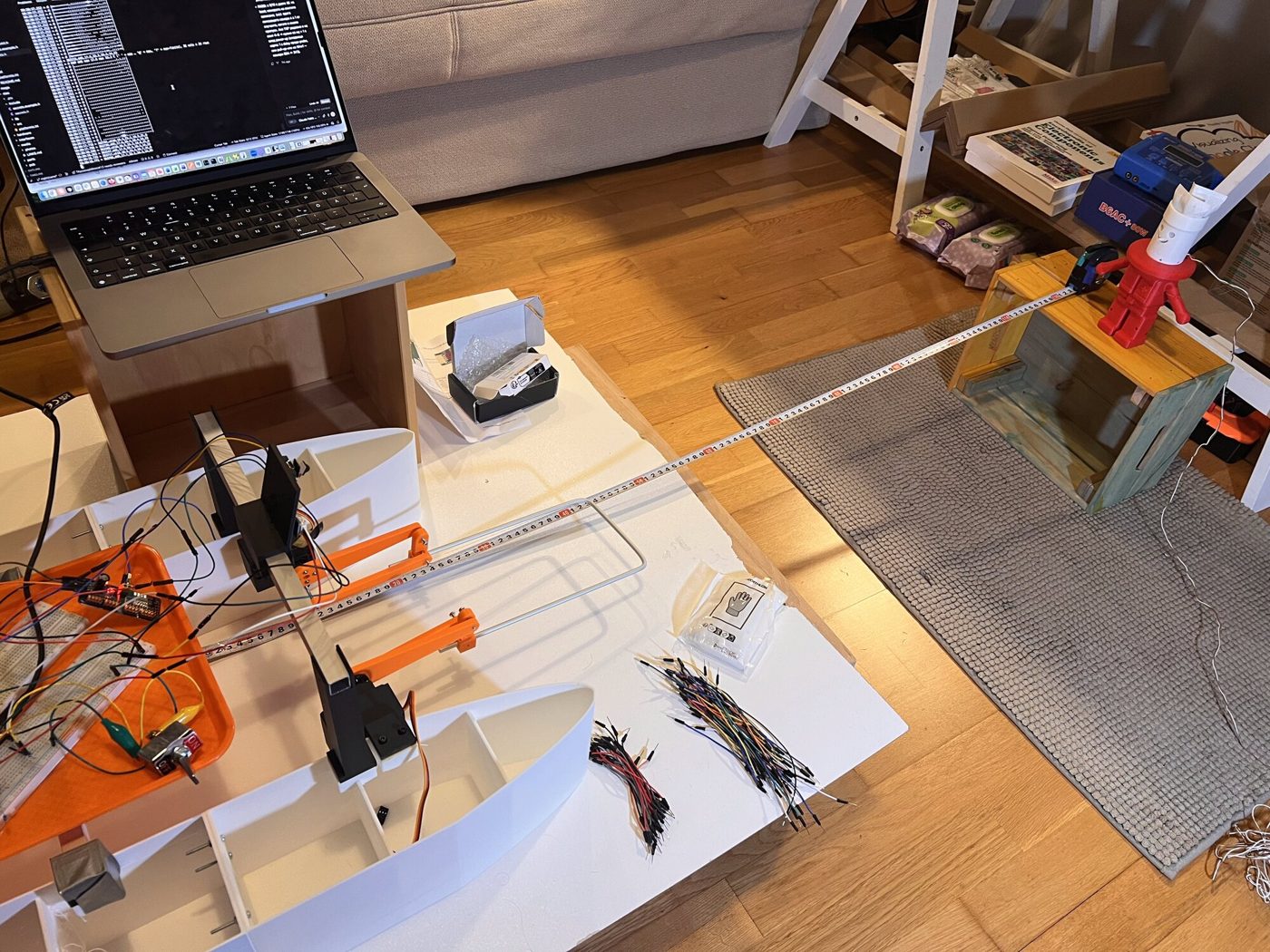
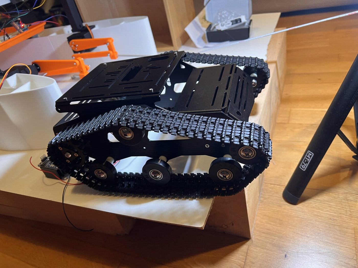
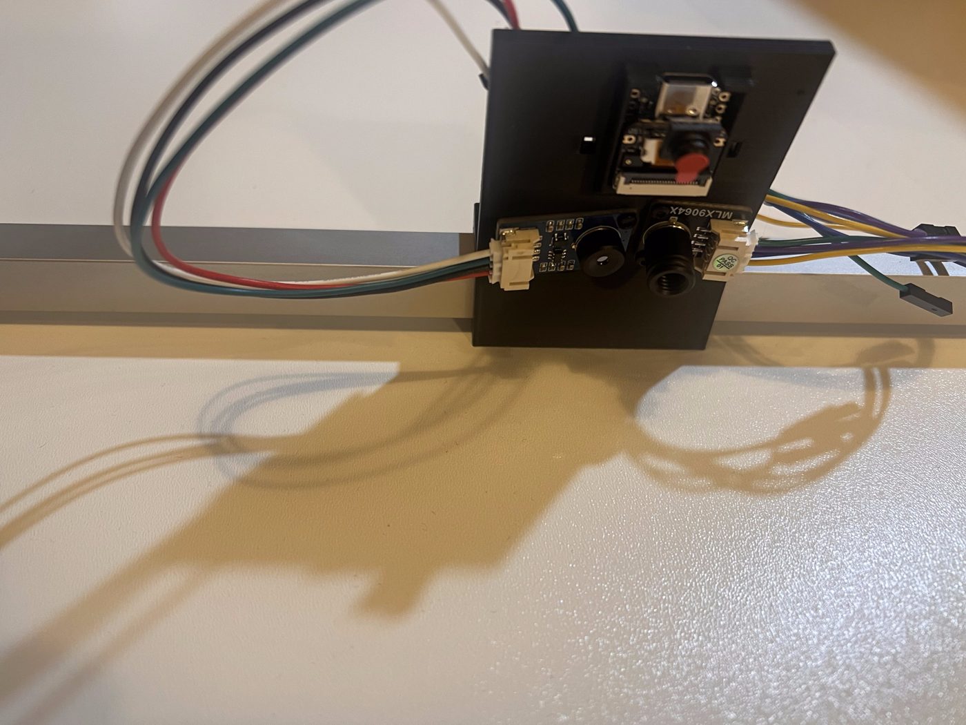
The small camera on the arch streams to the phone over its own WiFi: 640 × 480 at about 26 frames a second, the robot's-eye view with the cradle U and the orange arm ends in the foreground and Pesho on the floor behind; a 24-second run recorded to the microSD card. Before the antenna went on, the page showed 0 fps. Both thermal cameras wired to the controller: a wall test first, then Pesho's heated head at 0.5 m as a 15-pixel blob at about 47 °C on the narrow camera, and at 1.3 m a compact 2 × 3 pixel spot at 39.8 °C, while the 110° camera shows the head as one hot cell. In the evening the tracked chassis was assembled from the kit, gearmotors, side plates, wheels and tracks, in a little over an hour, and the left track turned from the controller through the BTS7960 driver: 12 V, under 0.1 A at low speed, 0.39 A at full, the run written to a CSV.
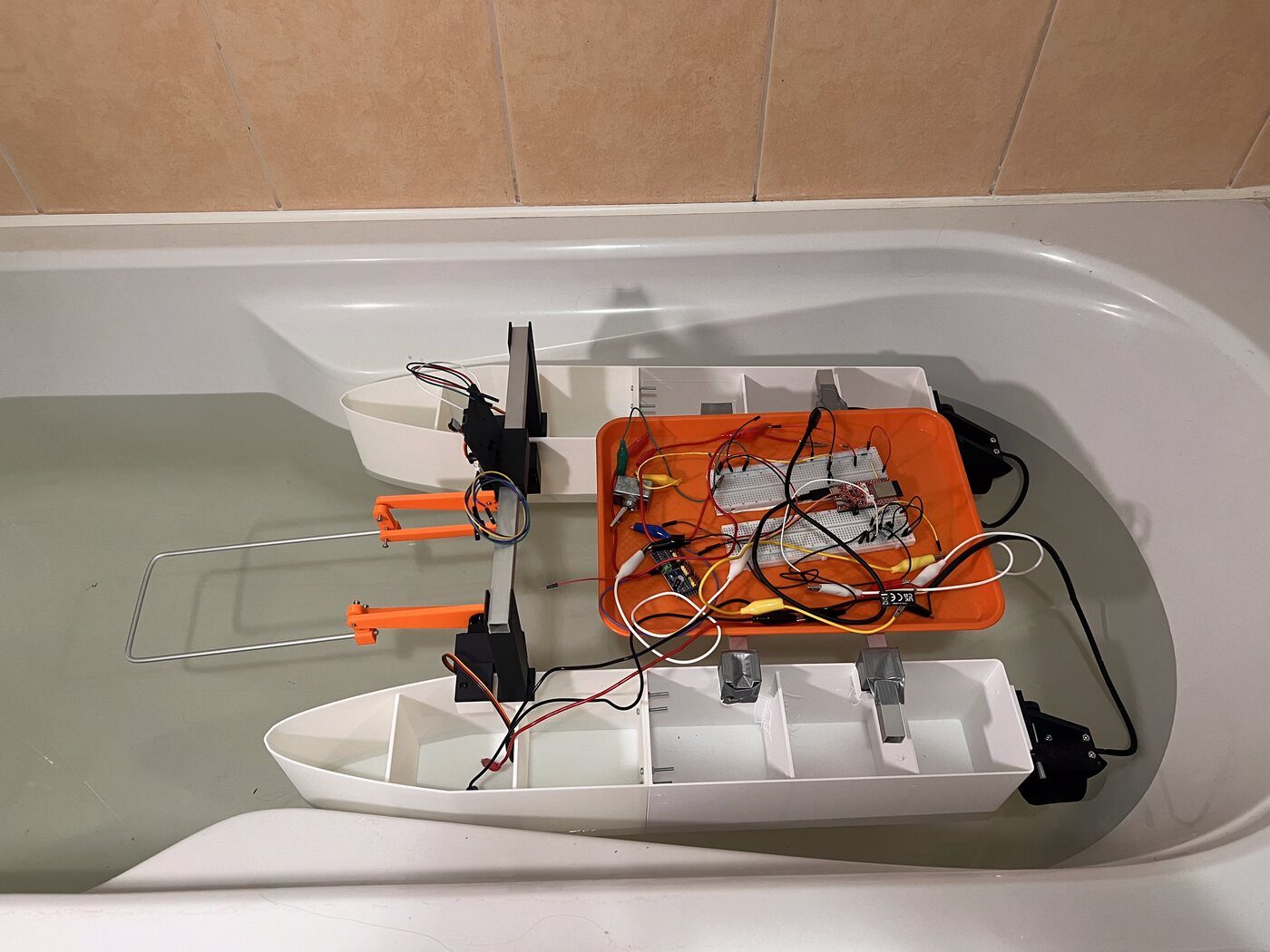
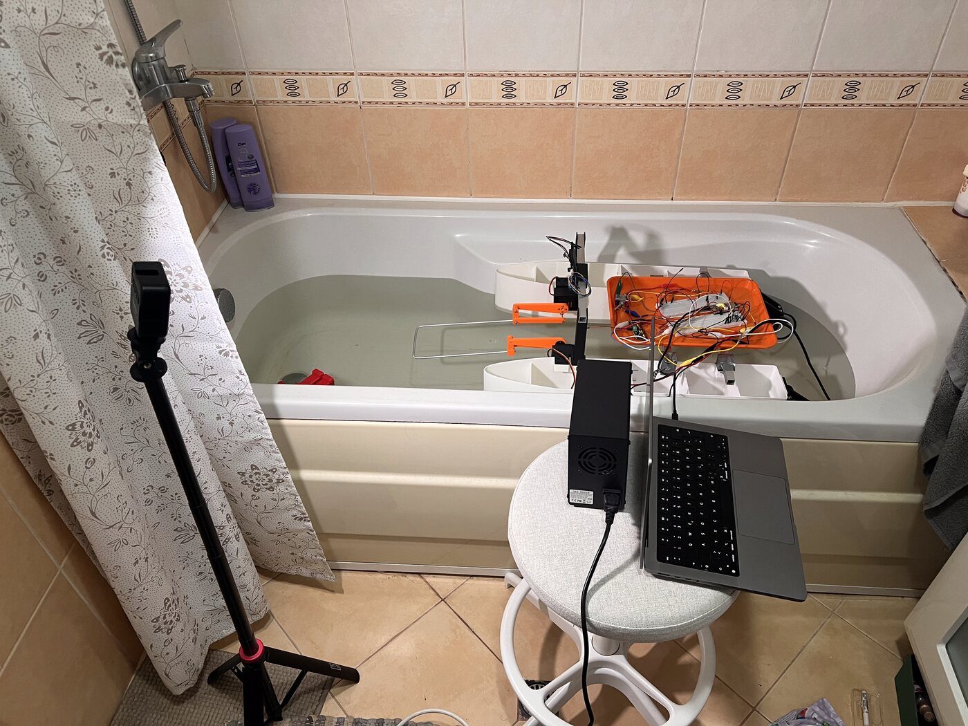
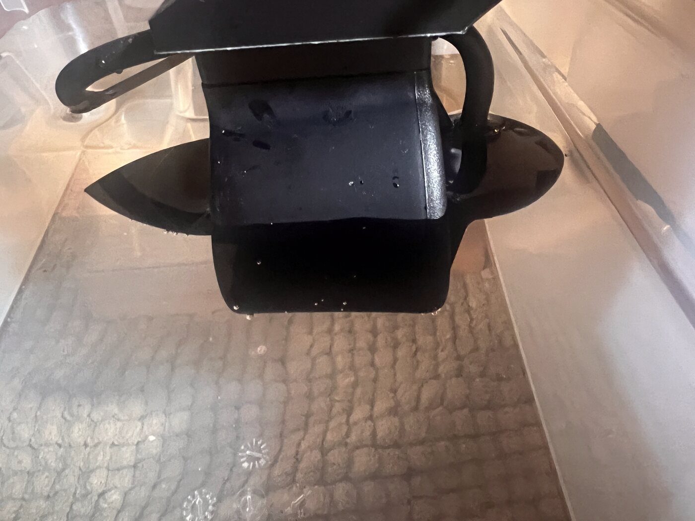
Morning: the thruster in a water box, spun from the phone, stick up and back. The second transistor stage for the right thruster went onto the breadboard, and the right thruster would not start: on 12 V it only clicks every 1.1 s, each attempt pulling the supply into its current limit at 2.13 A with the voltage sagging to 7.9 V. Signal checked, then swapped onto the working channel: still clicks, so its built-in controller or motor is faulty. The left one is fine. Rule from today: the duct fully under water with 2–3 cm above it, never run dry for more than ten seconds. Evening, 20:45: the whole AR-Mini in the bathtub for the first time, hulls, beams, arm mount and the orange electronics tray, tethered to the bench supply and the laptop, Pesho in the water as the target. It floats level, draft 20 mm, no water in the hulls after the run, and the one thruster pushes and turns it from the phone: 0.58 A at 1640 µs.
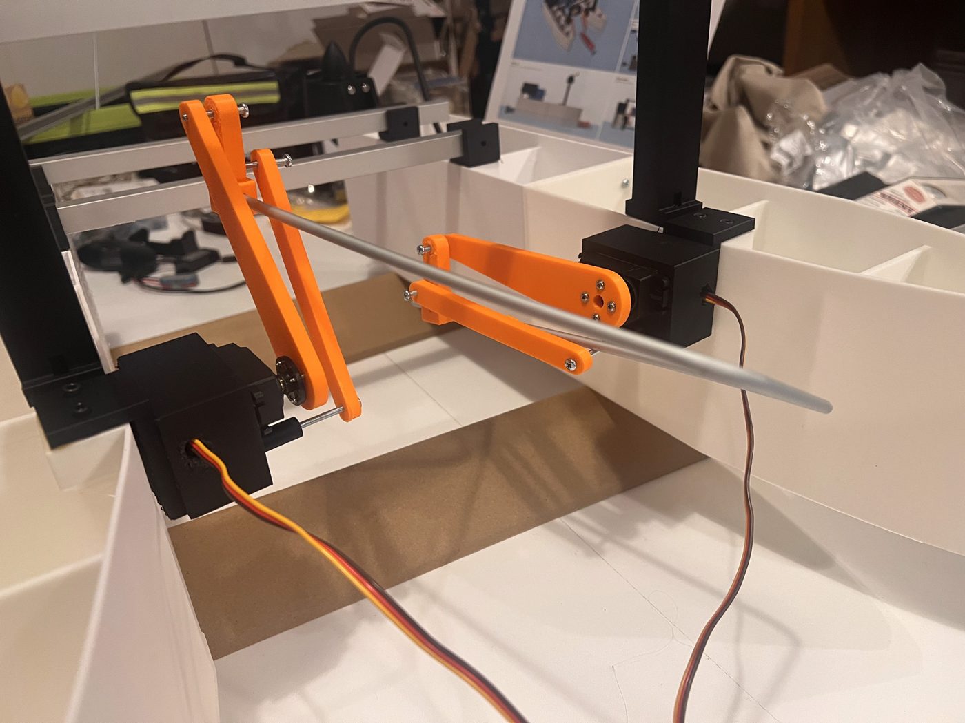
At 05:41 the arms were re-clocked on their horns and the pair sweep moved them together. At 05:56 the first powered lift: the empty U from deployed, ahead of the bows, to raised between the hulls and back, level all the way. At 06:32 the full cycle with Pesho: down, lift, hold, lower, about 0.24 A while lifting. The thruster arm fit: all four M4 × 12 in by hand, the Ø5 hinge turns freely; the duct ring is 42.95 mm, the 112 includes the cones. Pesho dry after 24 hours: 196 g against a 160 g reference, so 36 g of water stays in the vest. Leak. The battery divider was calibrated against the bench meter at four points, residuals under 0.02 V. Then the thruster spun from the controller through a one-transistor level shifter on 12 V: 1550 µs nothing, 1600 → 0.22 A, 1650 → 0.58 A, 1400 reverse → 0.21 A; the kill rocker while spinning put the signal to 1500 µs within 40 ms and the prop stopped. The fixed camera mount printed, 1 h 24 min and 39 g, and went onto the arch with both thermal cameras and the small camera board. In the evening the phone page on the controller's own WiFi: a false link-loss bug fixed; arm, then the kill rocker, gives safe; airplane mode and back gives safe disconnect.
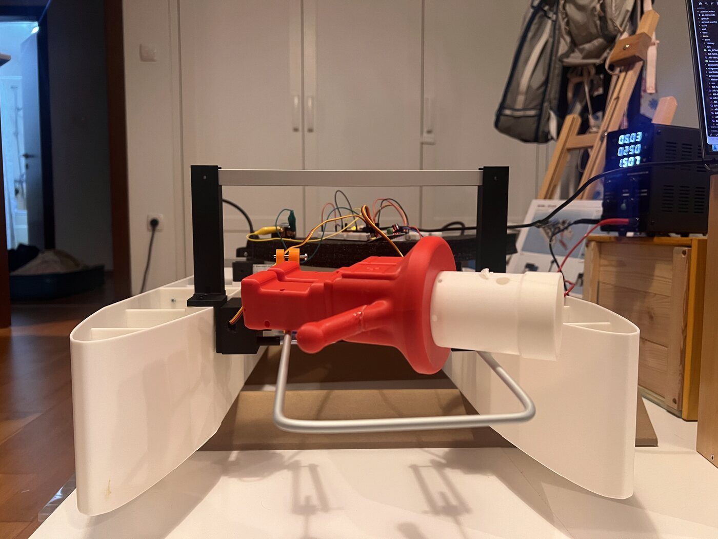
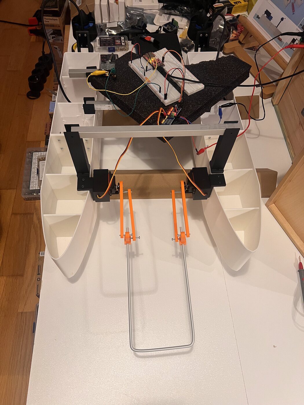
By 06:42 every mount was on both hulls. Pesho on the kitchen scale: 316 g, about 45 g more than his parts add up to, so the vest probably took on water overnight. The arch tube cut with a hacksaw and seated in both posts; both cross beams in their four brackets. The thruster's inserts turned out blind, 5 mm of thread, so the stock 28 mm M4 screws became M4 × 8. Hinge rod through, lock pin in: deployed, the duct hangs below the hull; kicked up, it clears the transom. Both thrusters on, and the whole boat stood on cardboard stands for the first time. The cradle U bent from Ø5 aluminium rod in the vise; with both linkages assembled it lifted Pesho by hand. In the evening the two servos got their first pair command. SDA and SCL were on the wrong pins, then the bus found the driver at 0x40, and the first command with the U in twisted it: the arms went to different poses, 0.53 A, kill. Fail.
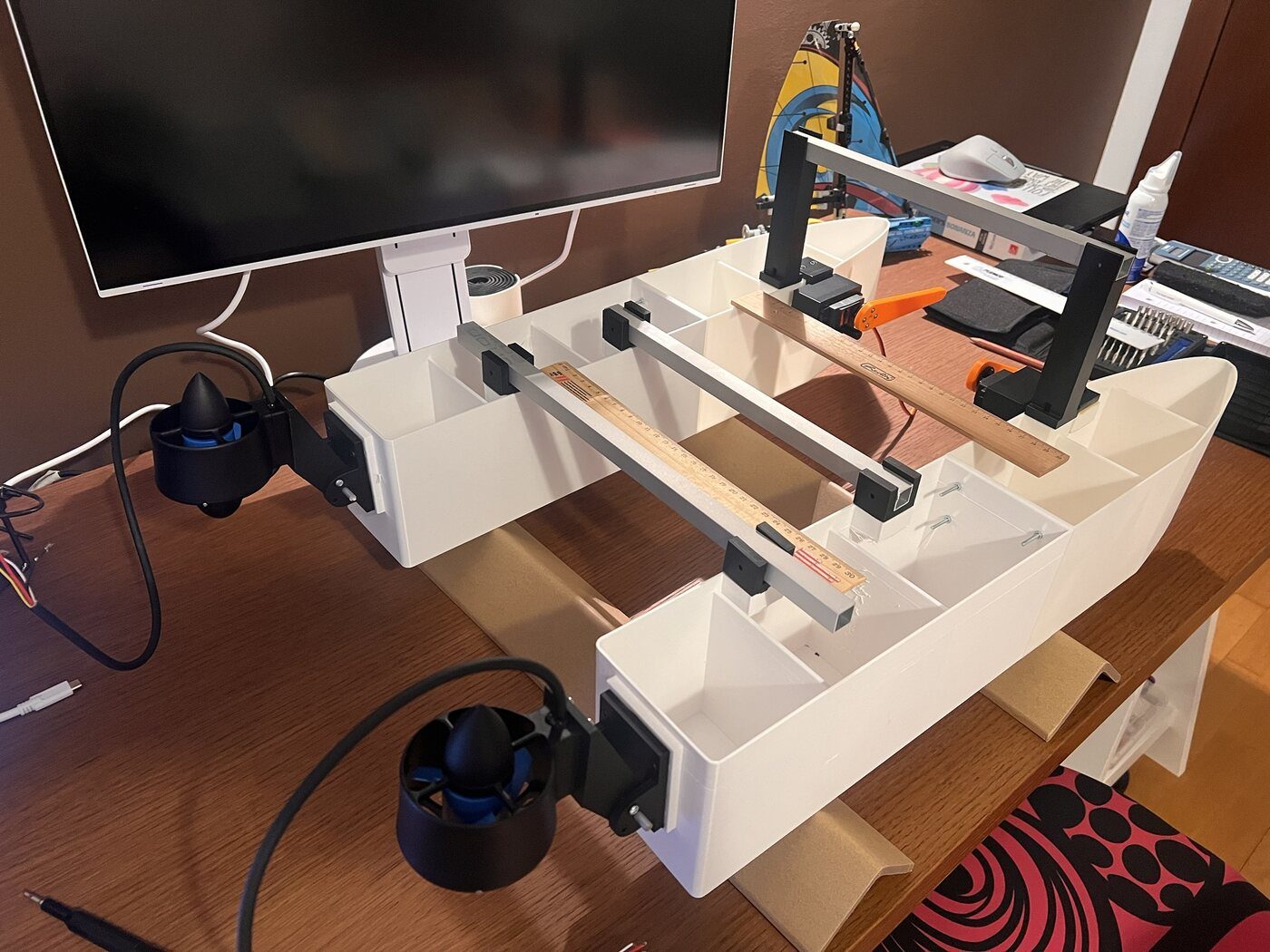
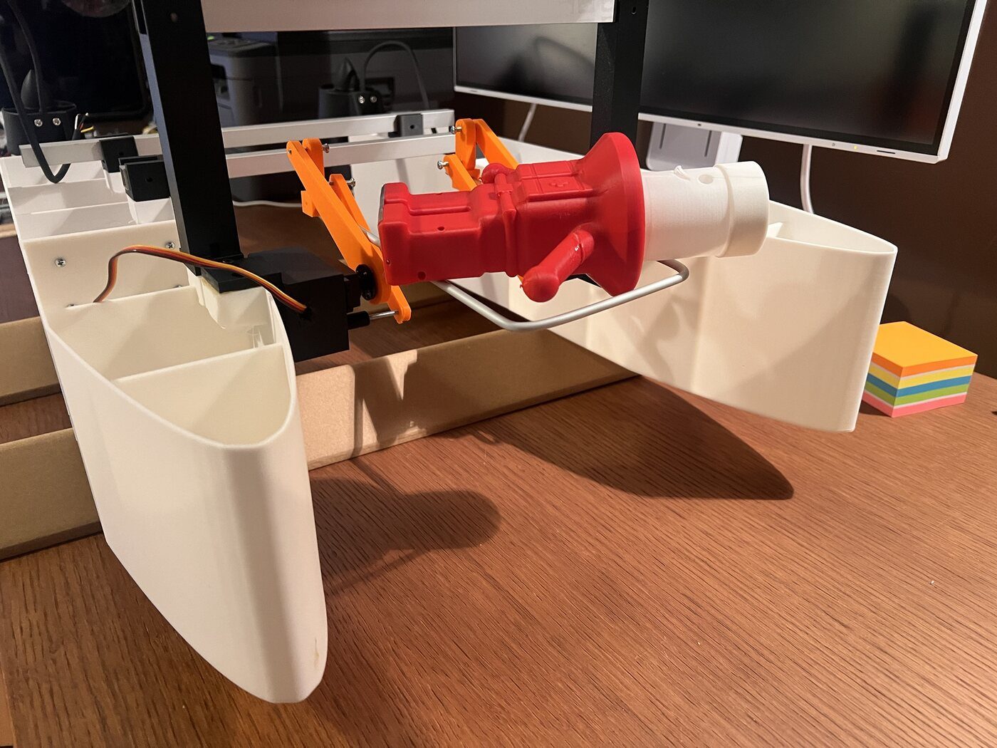
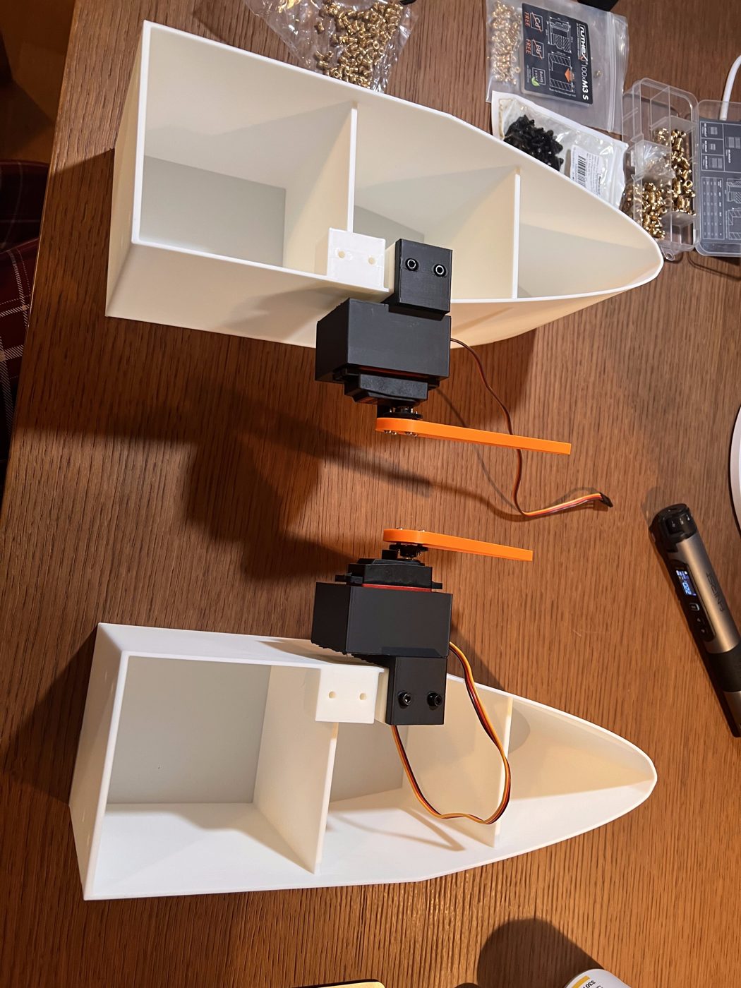
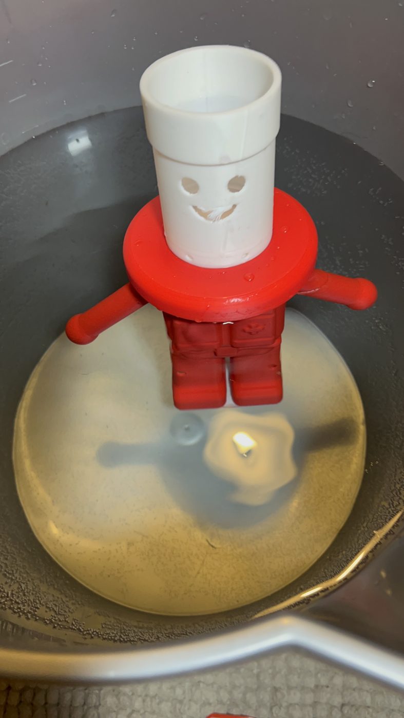
The pivot bracket with its servo bolted onto the hull boss with two M3 screws into brass inserts; the arm swung by hand from down to horizontal to vertical. The mirrored second bracket followed on the other hull in four minutes. The thruster went into a mop bucket on the bench supply: 9 V, 9 mA idle; the yellow signal line idles at 4.98 V behind a pull-up of about 4 kΩ and white is signal ground, so the built-in speed controller wants a plain servo pulse. Pesho's left arm glued back on; body 132 g against about 100 in the model, head and lid 28 g. Without ballast he tips over; with two nuts taped into each boot he floats upright, head and shoulder ring out of the water. In the evening the 24-insert round: eight in the transom pads, eight in the beam bosses, four in the arch posts, four in the pivots, all M3 brass with the iron at 220 °C. Both thruster brackets bolted to the transoms.
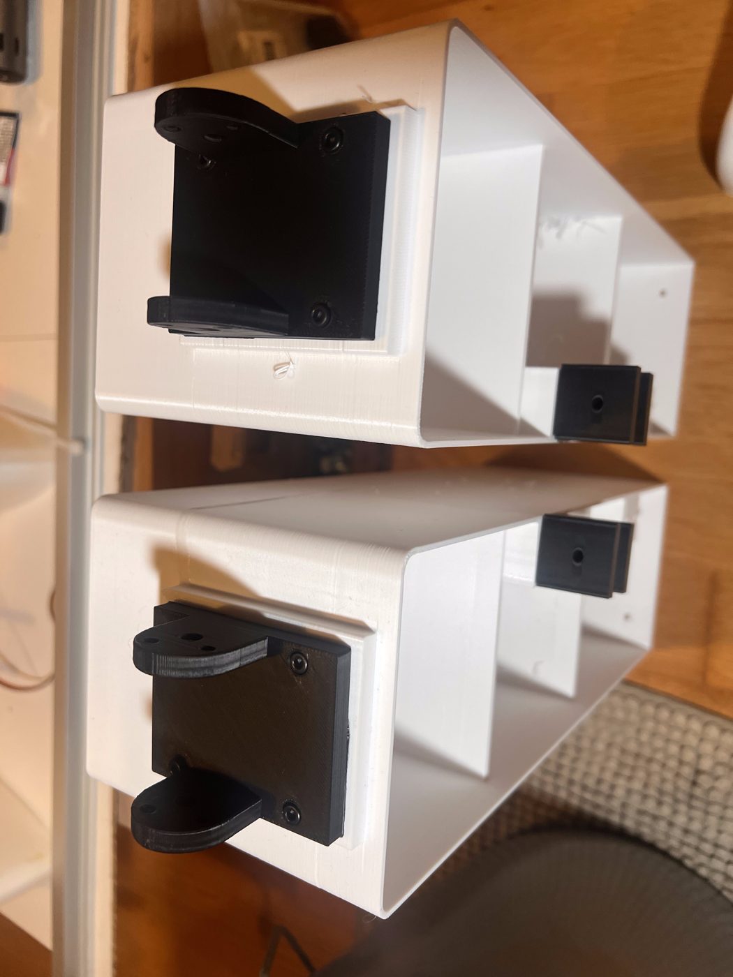
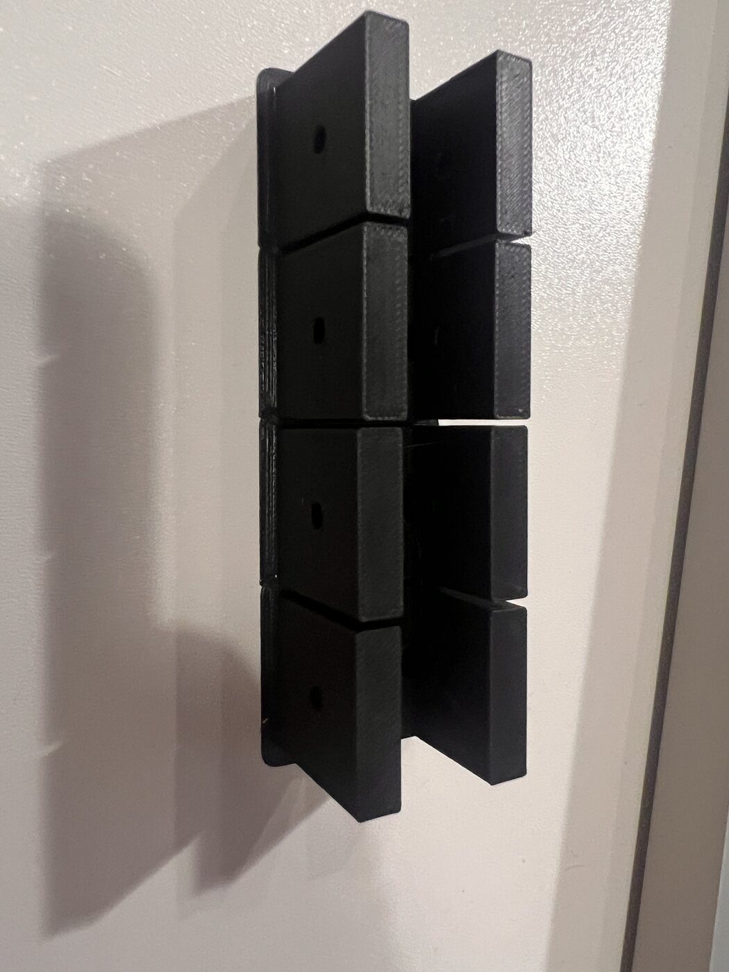
Eight beam brackets on one plate, black PLA, 1 h 14 min and 39 g. Dry fit: one 15 × 15 mm aluminium beam across both hulls, the brackets sitting loose on the rims at both beam stations.
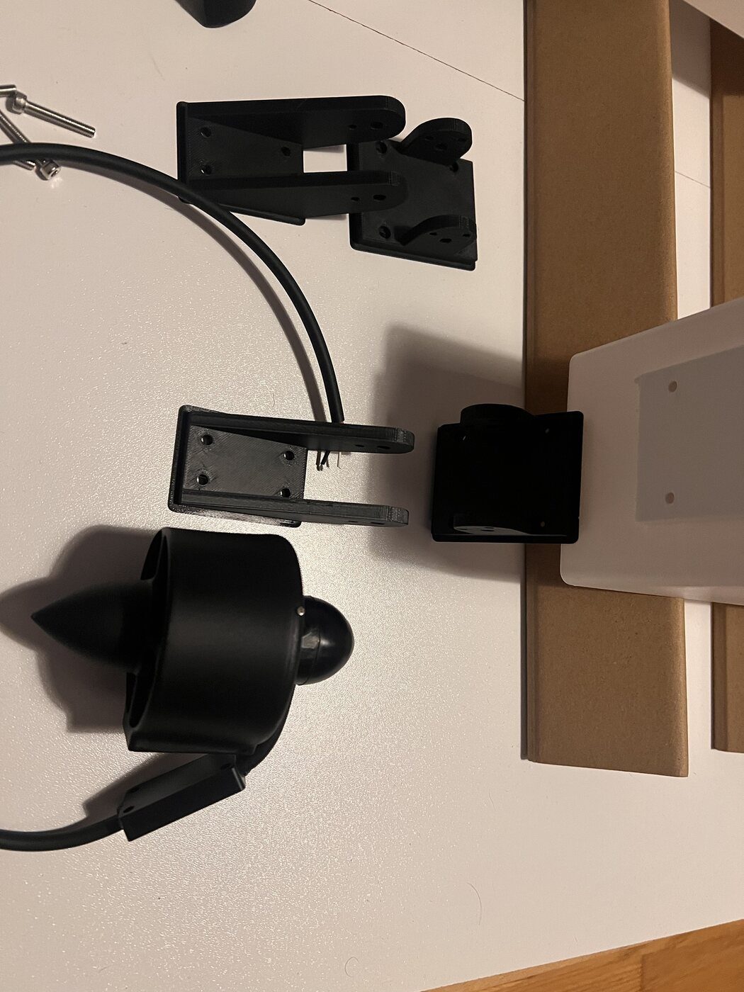
The kick-up mounts for the thrusters printed overnight: two brackets and two arms in white PETG, 2 h 52 min and 96 g, after a CAD fix that moved the hinge pin 5 mm outward. Tree supports only under the two pin bosses; the 37° underside of the cheeks printed clean without any. Offered up: the arm plate on the thruster's four-M4 pattern, the bracket on the transom pad of the hull.
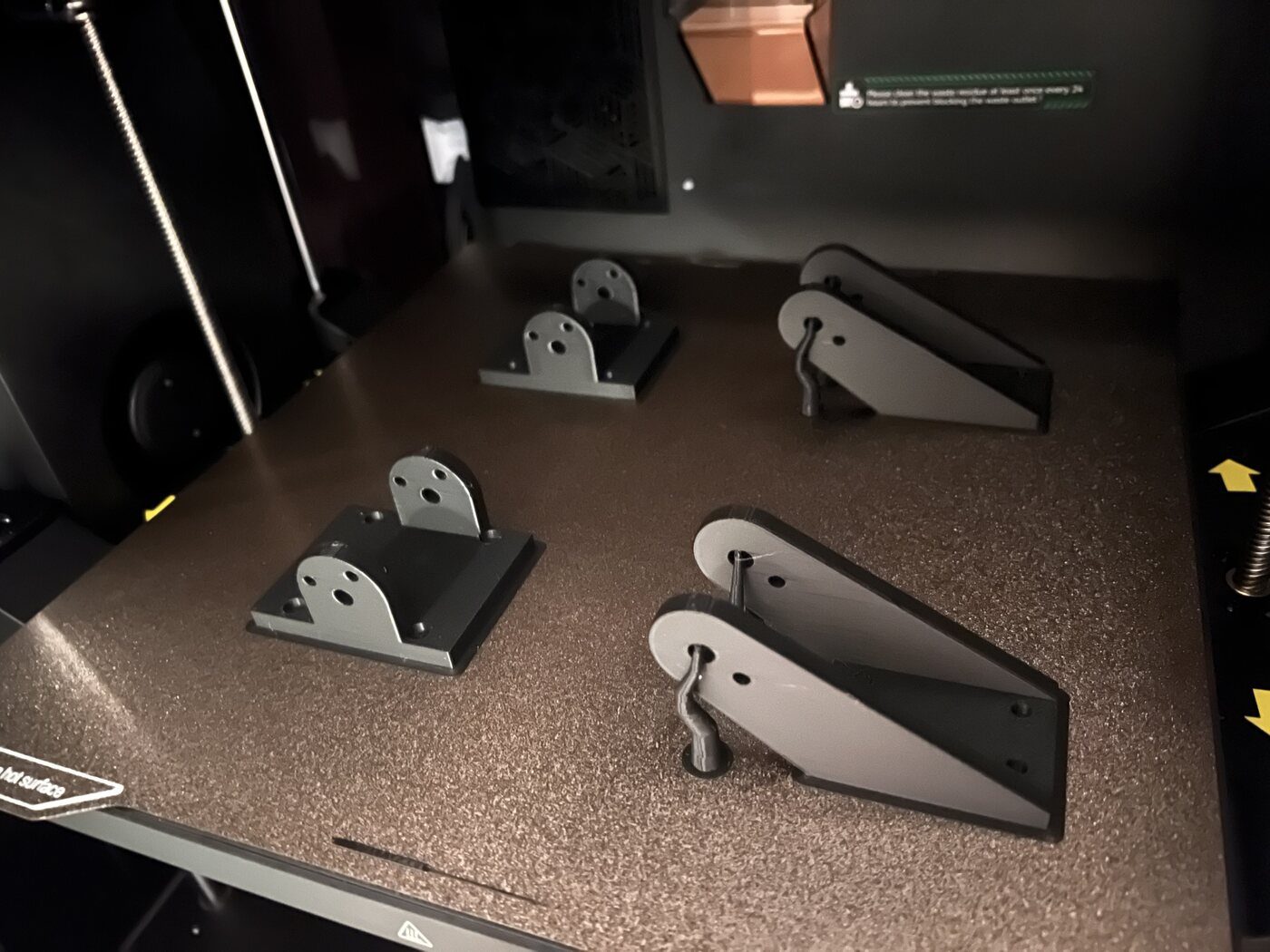
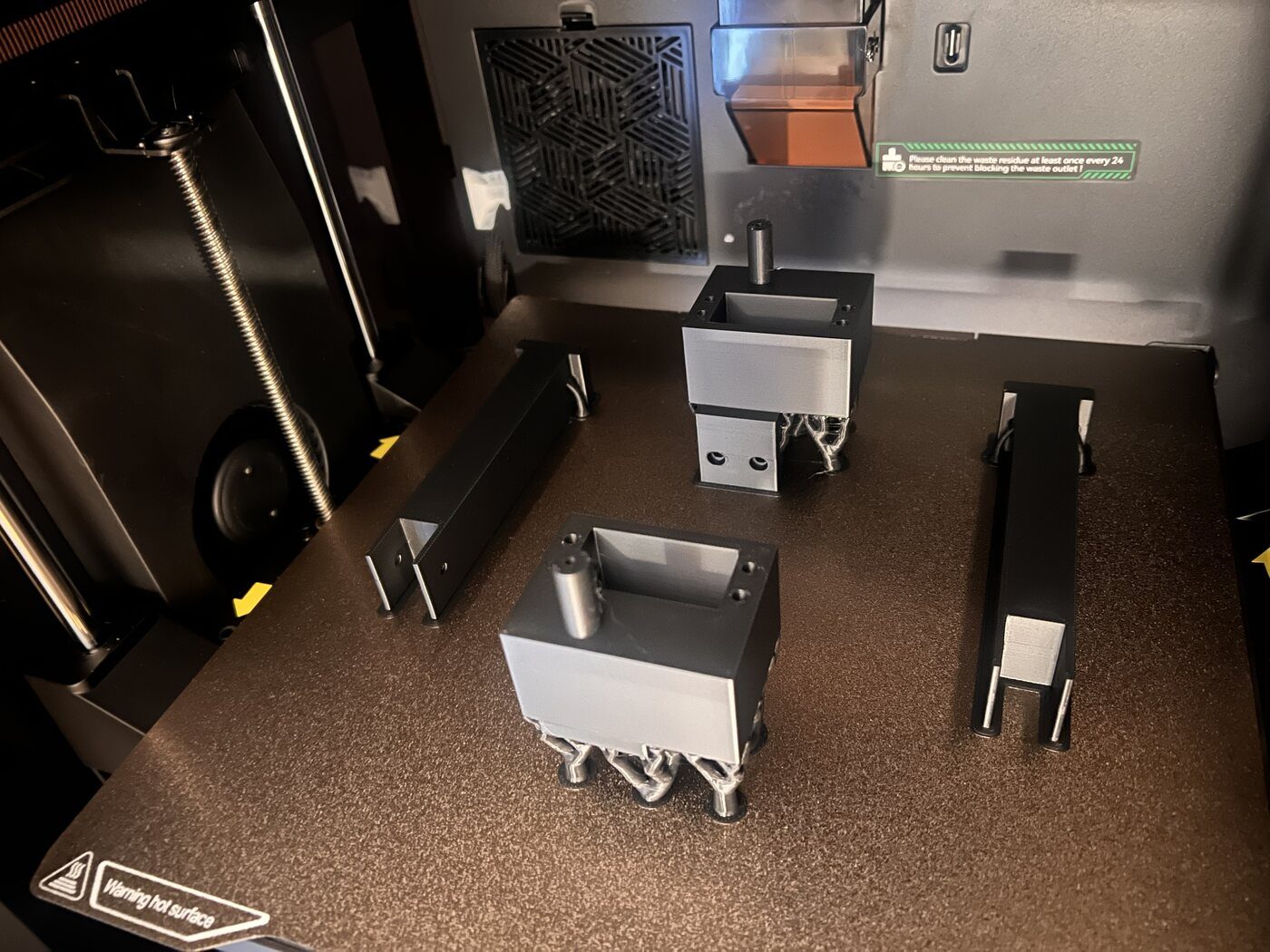
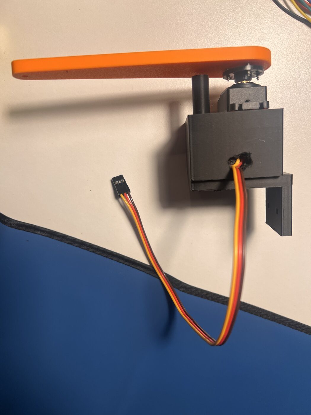
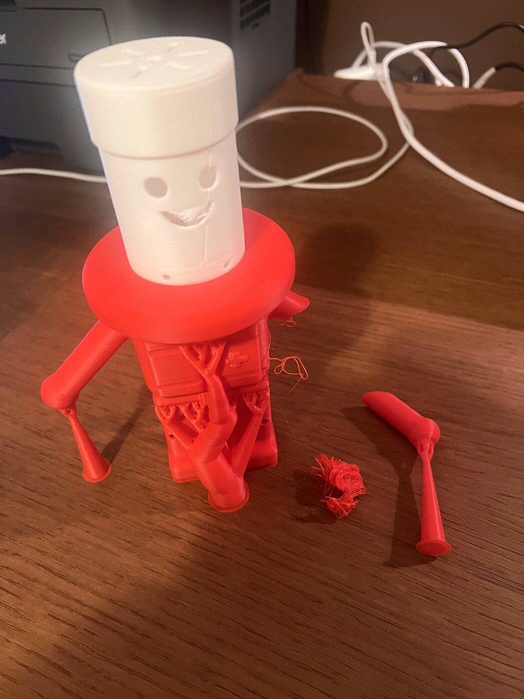
The black plate printed in the morning: two pivot brackets, mirror images of each other, and two arch posts, 5 h 45 min and 176 g. First dry fit at 17:11: the servo stopped 16 mm high, its cable outlet sitting on the rim of the pocket. The pocket had no slot for it. Fail. By 21:48 a hole was drilled on the workstation, the servo sat flat and the drive arm swung on its disc horn; the CAD gets a cable slot. The modules for carrier rev B were measured with the caliper before the board goes to Aisler: the servo driver is 58.98 × 25.92 mm, not the 62.15 in the bill of materials. The kill switch is a plain SPDT rocker now, with the controller reading the enable wire through a divider: a broken wire reads as KILL and the motors are off at the same time. The last Amazon batch arrived; nothing is left in Ordered. In the evening Pesho's head and lid printed in white PETG, then his body in red PLA until 01:07; the left arm snapped off as the part came off the bed. Glue, and a shoulder boss in the CAD.
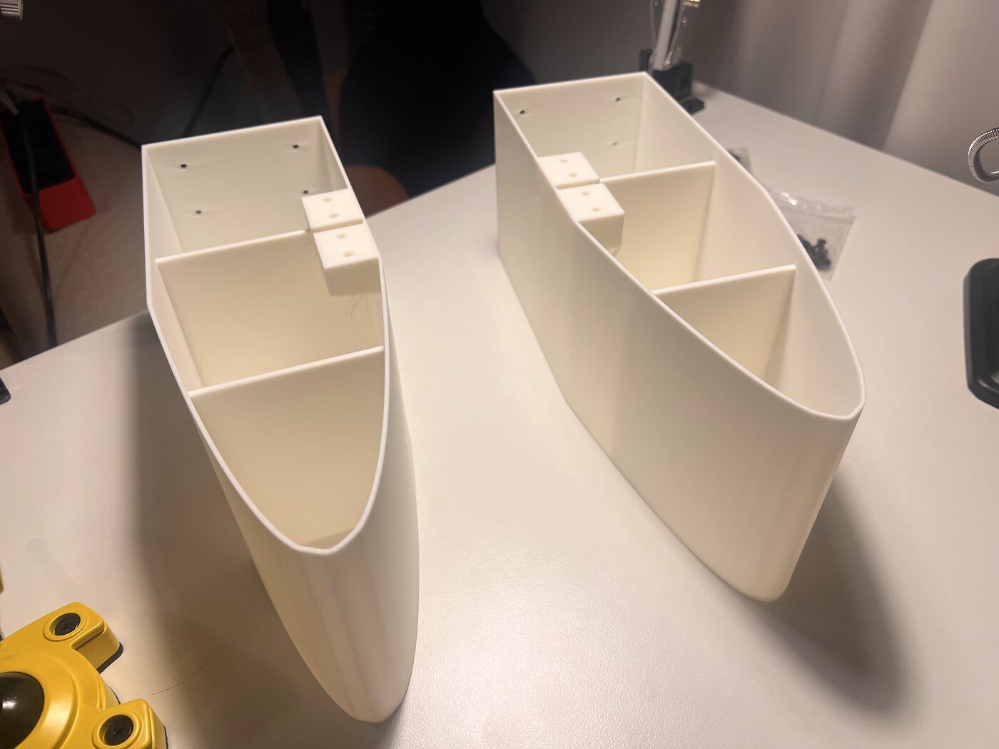
The mirrored right hull finished at 04:55, 6 h 17 min and 345 g, and left a thin layer on the white PLA spool, so the aft hulls went to white PETG: the left one 7 h 30 min and 410 g, done at 16:36; the right one started at 16:52 and ran past midnight, 7 h 34 min. PETG strings everywhere, cosmetic. At 16:44 every v1 part was on the desk together for the first time. In the evening the second Amazon batch came with the lab supply (0–30 V, 10 A), four bus servos, a Raspberry Pi 5, the thermal camera for the cradle and the IMU. Pesho v3: the hand warmer measures 82.6 × 52.3 mm and weighs 45 g, not the 30 the model had guessed, so the head became a capsule with the warmer rolled against its wall, a shoulder ring holds the head out of the water, and the nuts go low in the boots.
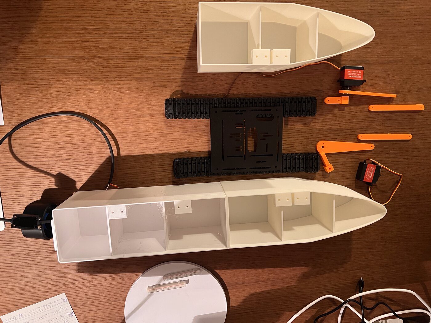
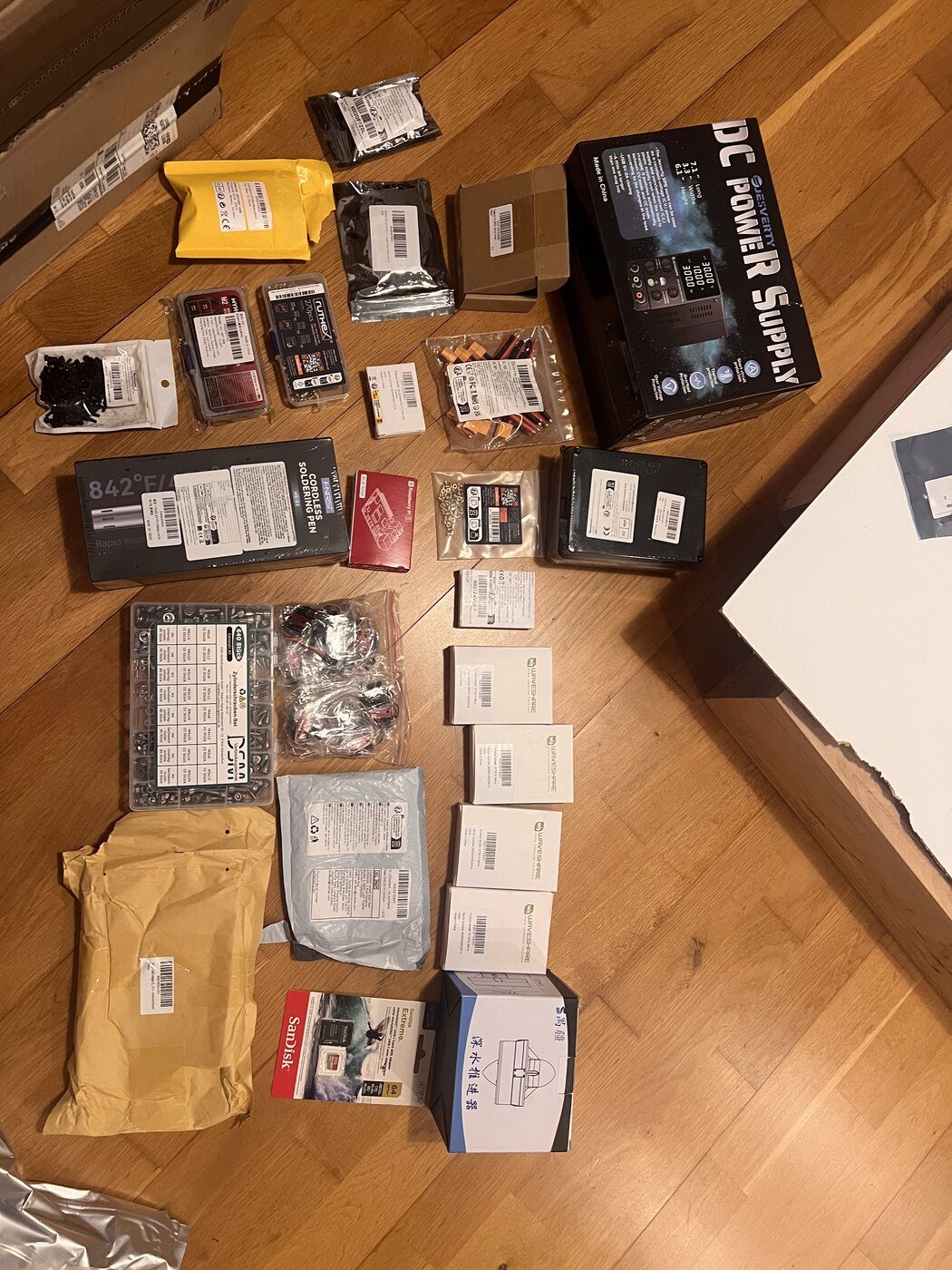
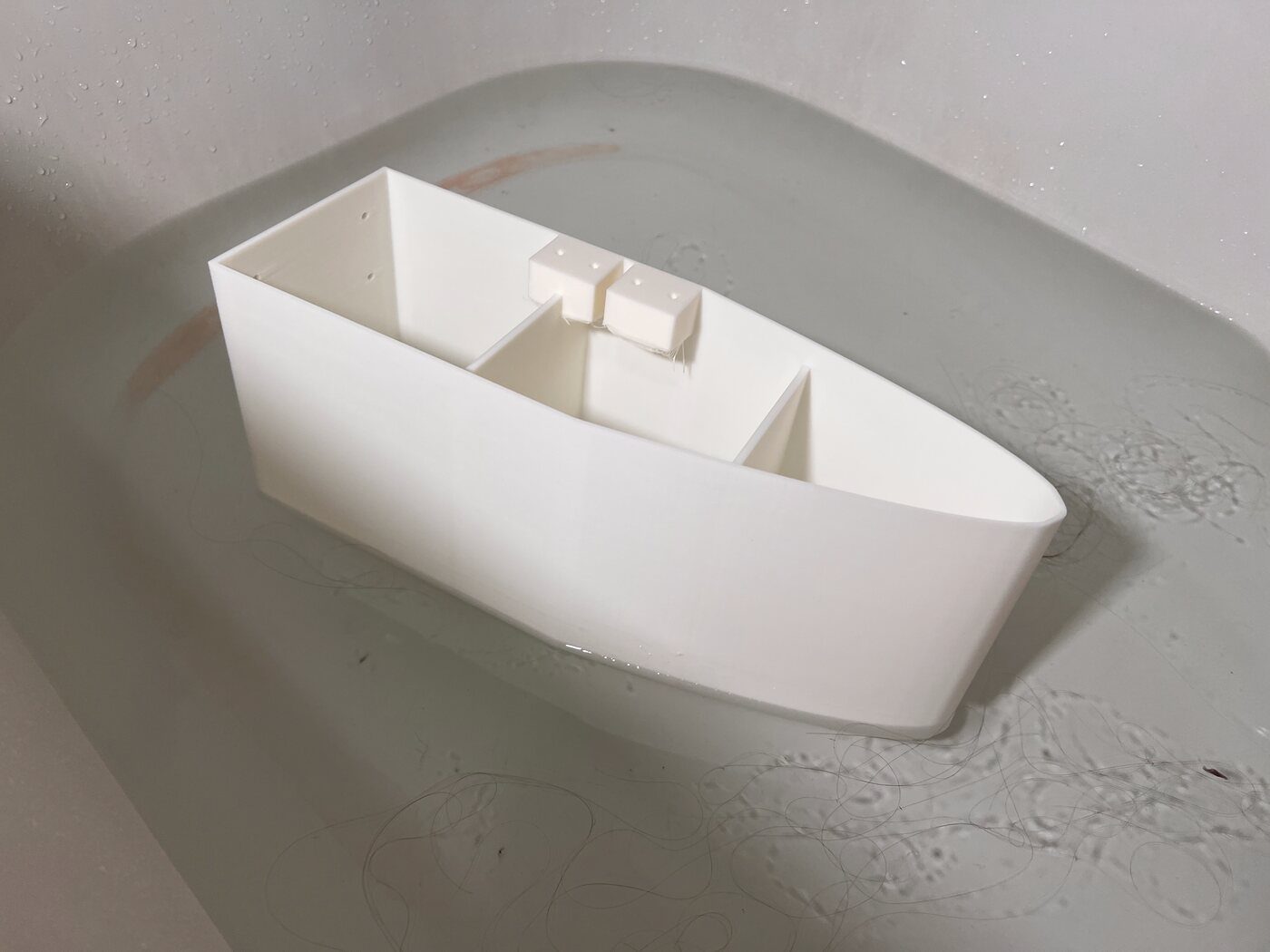
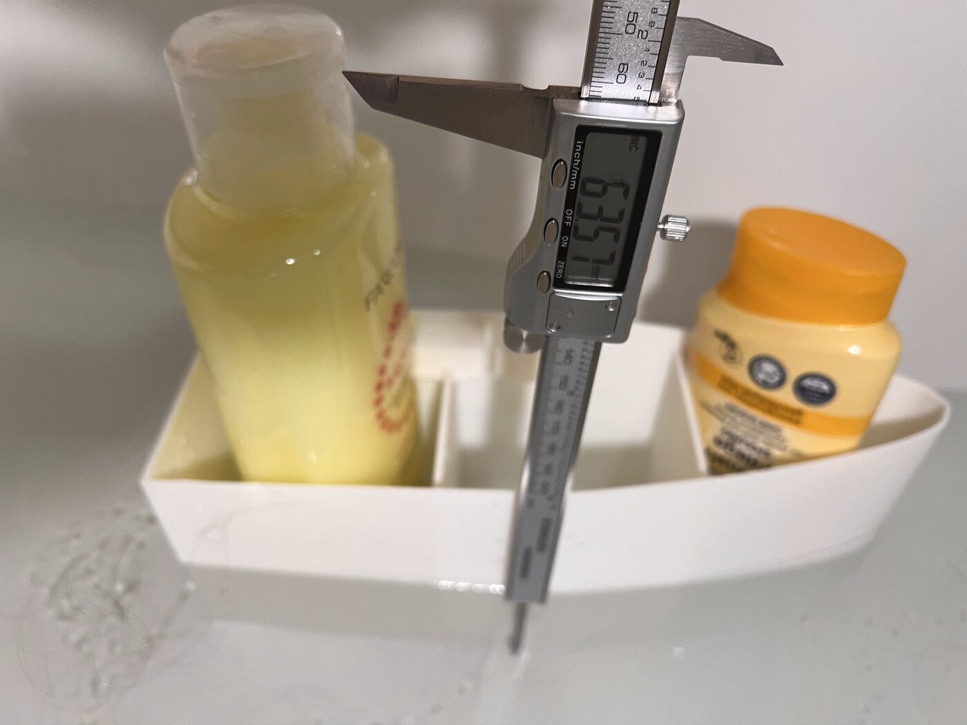
The orange plate printed before dawn: a drive arm, two idler arms and two couplers, 1 h 12 min and 41 g. The first hull section followed, 6 h 13 min and 345 g on the screen, 323 g with the brim and supports off, 119.70 mm tall against 120 in CAD. In the bathtub at 15:18 it floated upright with no heel, 12.99 mm of draft against 12.7 predicted. Loaded with 1.374 kg of water bottles it sat 63.57 mm deep with the stern trimmed down, and the inside was dry after fifteen minutes. Pass. The mirrored right hull started at 15:45 and printed through the night. A meter on the DevKit at reset and boot: GPIO39 comes up HIGH after reset when the code does not drive it; that card stays open until the pull-down check is repeated. In the repository the week's night tasks landed on main as release r1a: the mission state machine, the safety layer with its latch, bench sketches for six modules, the parts agent that watches suppliers and the tool that cuts the release video from the card photos.
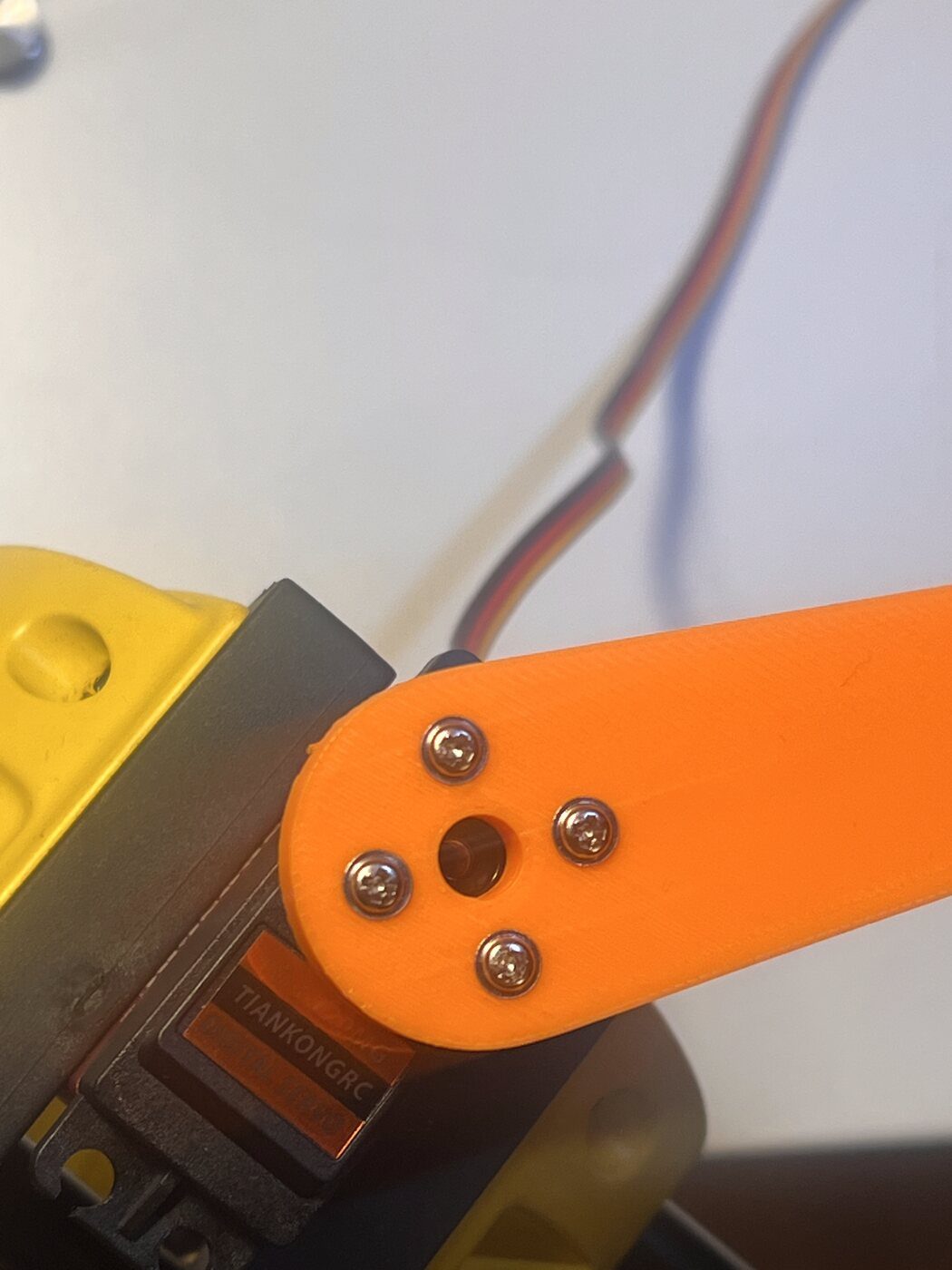
The v1 controller is now the Olimex ESP32-S3-DevKit-Lipo, designed and made in Plovdiv: 36 usable pins instead of 11, so the kill switch and the leak probe get their own inputs. A perfboard carrier is soldered now while a PCB carrier is ordered from Aisler in parallel (decision 0005). The thruster bolt pattern was re-measured from inner and outer edges: 35.0 × 15.9 mm, not the 15.6 guessed two days earlier. The servo was re-measured for the arm pocket: ear holes 48.26 mm apart, not 50; with 50 the screws would have missed the inserts by a millimetre each side. Caught before printing. The first print after the jam came out thin: the nozzle was at 140 °C. Set the filament source and the temperature, sliced again, and the drive arm printed clean in 20 minutes, 13.0 g. In the evening it went onto the servo's disc horn with all four screws. Fit: pass.
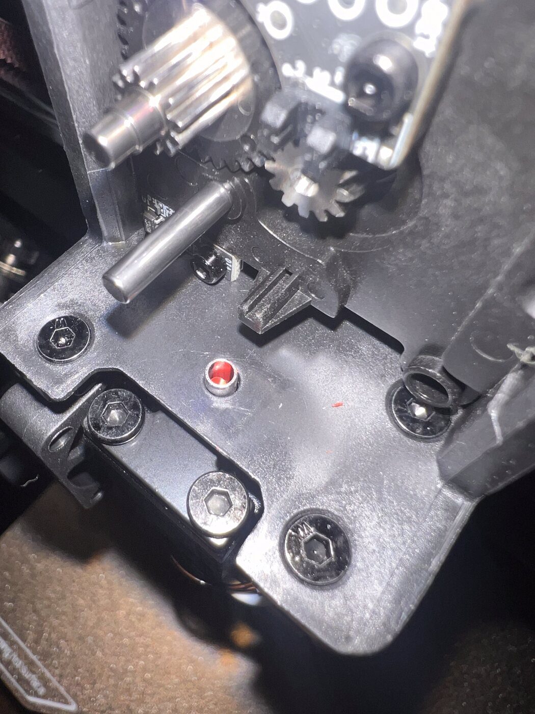
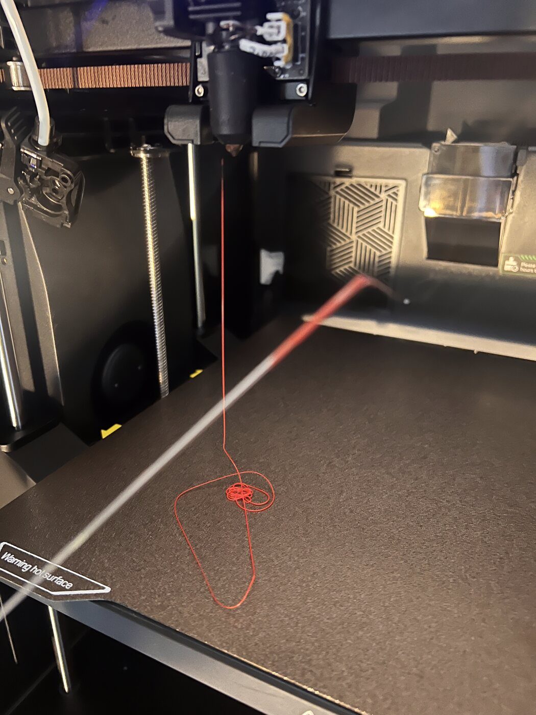
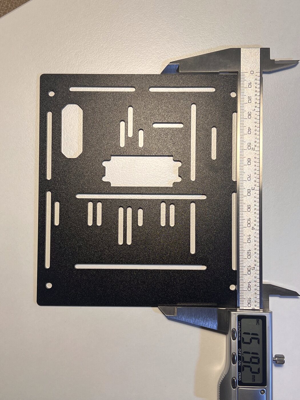
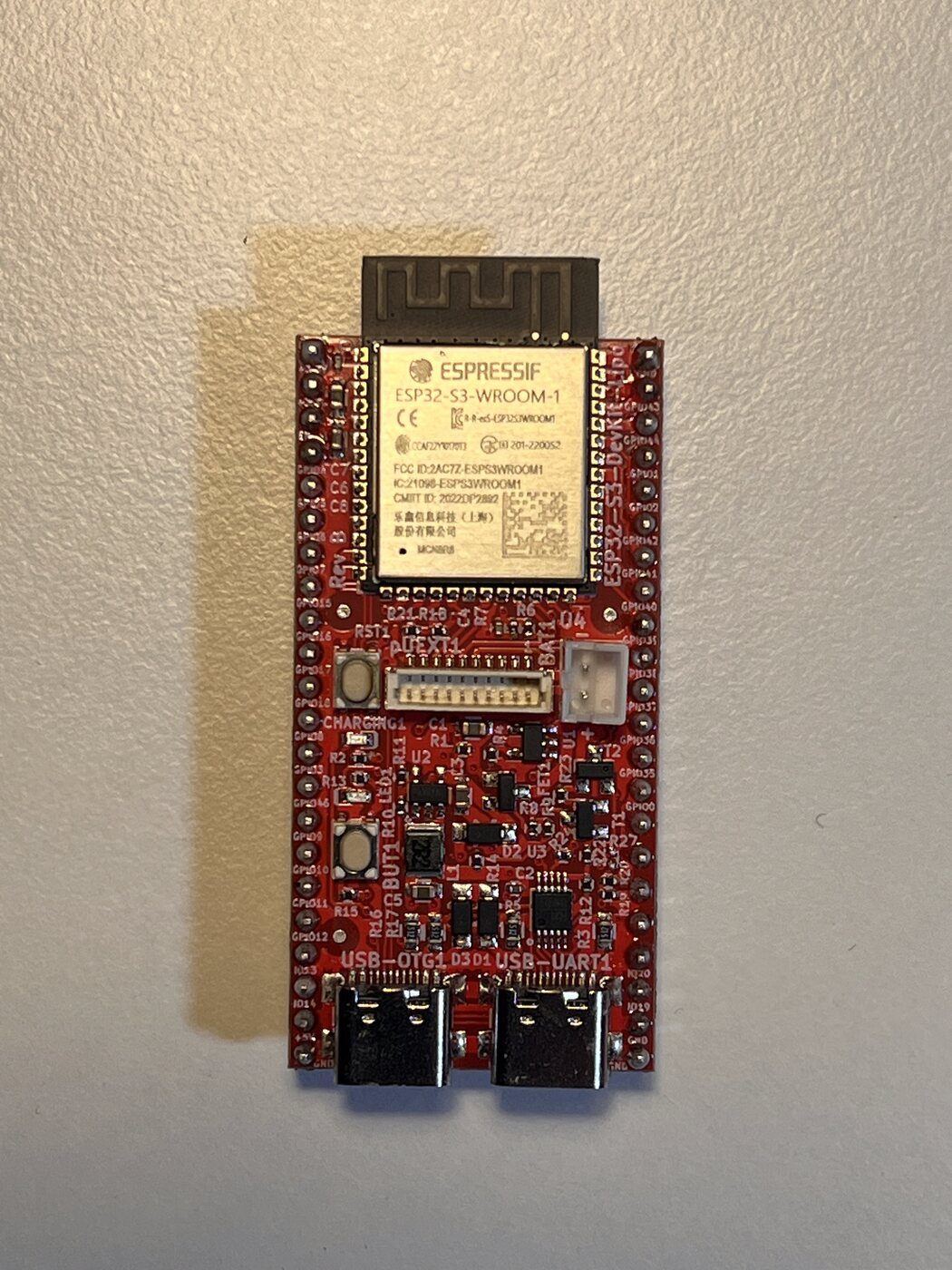
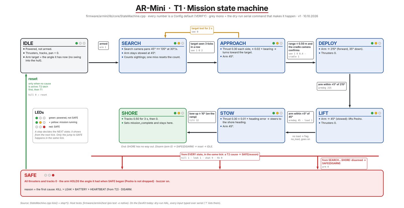
Card C003: the chassis plate measures 151.8 × 134.8 mm and its slots land 10 mm off the beams. Fail. CAD v2.0 moves the chassis to x = 300 and, from the thruster numbers of the day before, puts the thruster on a kick-up hinge on the transom with its pin above the waterline: nothing below the waterline, and it folds up on shore (decision 0004). The test tracker became a kanban board with cards C###. The first night task, the mission state machine, was reviewed and merged, and one of its assumptions was checked against the real board under the lens. The printer started printing in the air: a filament-detector error, then the head drawing the part with nothing coming out.
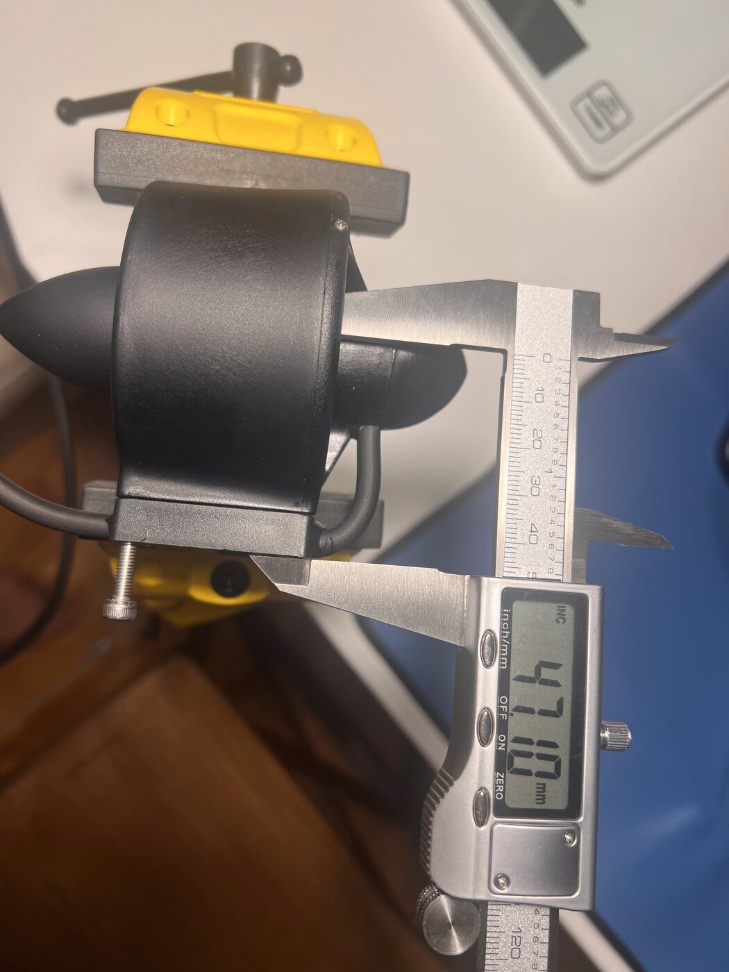
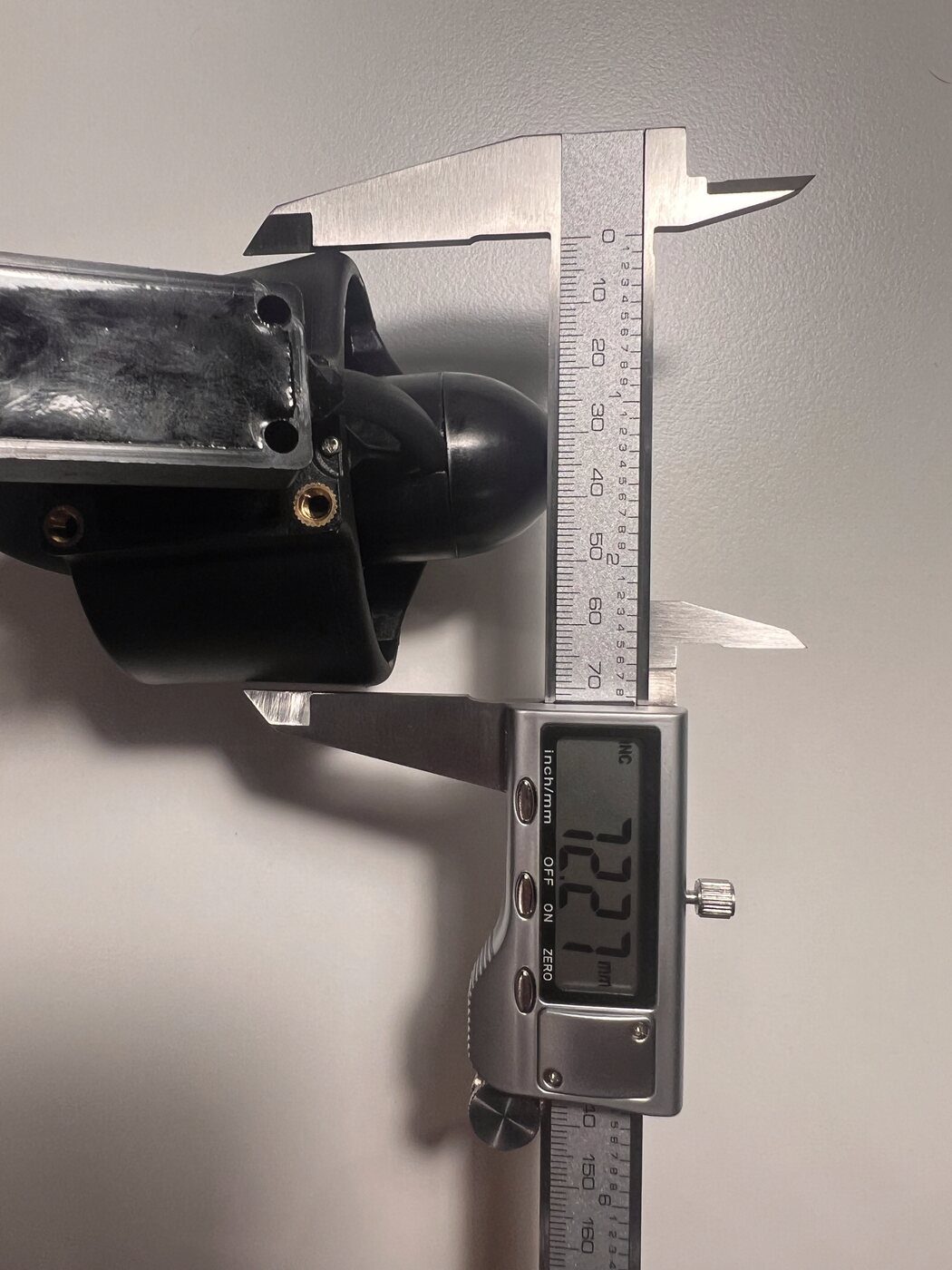
Card C001: the duct is 72.27 mm across, not the 77 on the box; 112 mm long; mounting face 47.10 mm above the propeller axis; 201 g. A 72 mm duct cannot sit under a 42 mm waterline on a flat pad, so the stern mount in CAD v1.9 was wrong. Card C002: four wires, no shorts, asymmetric resistances, so the speed controller is inside. Pass. Lesson: measure the bought part before drawing its mount. The first night task went to a background coding agent.
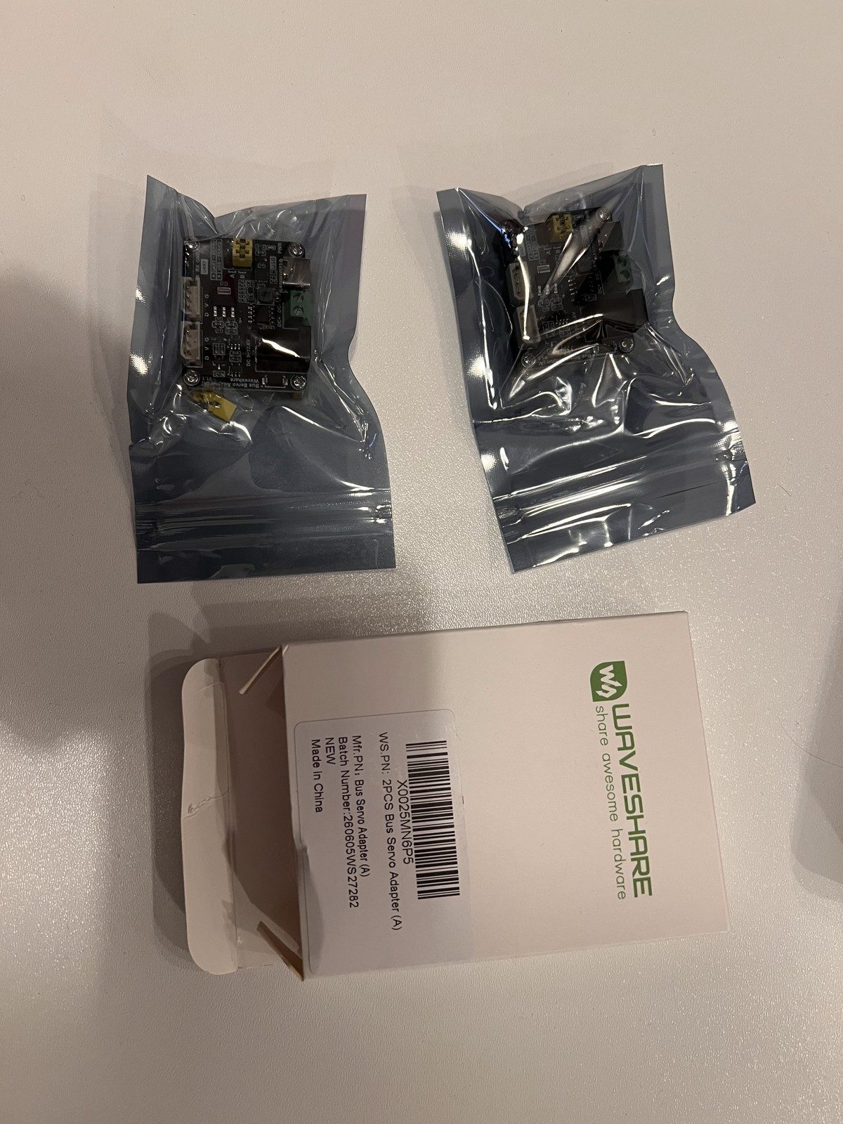
The 3D model showed the cross-beams running straight through the power box, so the box now sits on top of them (CAD v1.9). The connector list is settled on JST-XH. The thruster and two bus-servo adapters arrived; the thruster is 112 mm long and mounts from the top, which the CAD did not expect. Three DevKit-Lipo boards ordered from Comet. The ARmini repository exists from today.
32 violations on the first pass, two of them real: starved thermal reliefs on two ground pads, fixed with solid zone connections. The interim servo was measured and the CAD went to v1.8. Seven colours of filament now mean seven things: orange moves, black holds, blue encloses, red is Pesho.
Aluminium beams, fasteners and the fuse block. The BOM is now a dated file, not a chat.
152 × 135 × 66 mm, CAD v1.7. The rev 0 breakout board is drawn.
CAD v1.4 to v1.6 after measuring the real chassis and servos. The test dummy is designed: 19–20 cm, floats head and shoulders out, heated to body temperature.
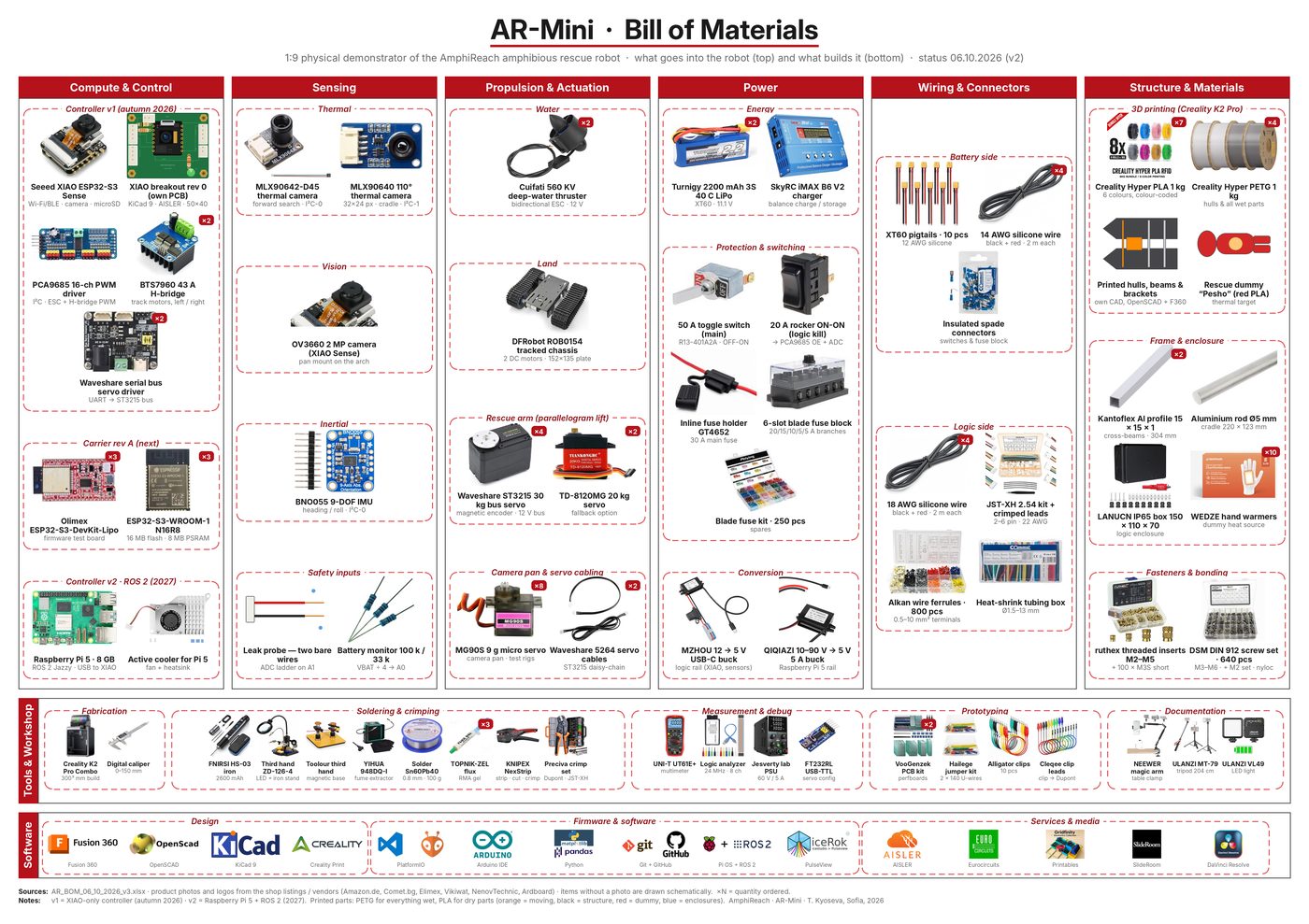
The AmphiReach README now lists every result in the revised paper with the commit, the script and the output file that produced it. Tool decisions and the bill of materials for AR-Mini are fixed the same day.
The revision requested by the reviewers is finished and resubmitted to the National High School Journal of Science.
Seven listings rejected: fixed-speed pumps, bare motors, surfboard kits. The rule from now on: the title must say thruster, give a thrust figure and include a bidirectional controller. Lithium packs chosen and bought locally.
The plan was a small quadruped. Its motors and boards turned out to be unobtainable outside China, so the physical project became what it should have been from the start: a small AmphiReach. Scope written, CAD v1.0 to v1.2, first orders placed.
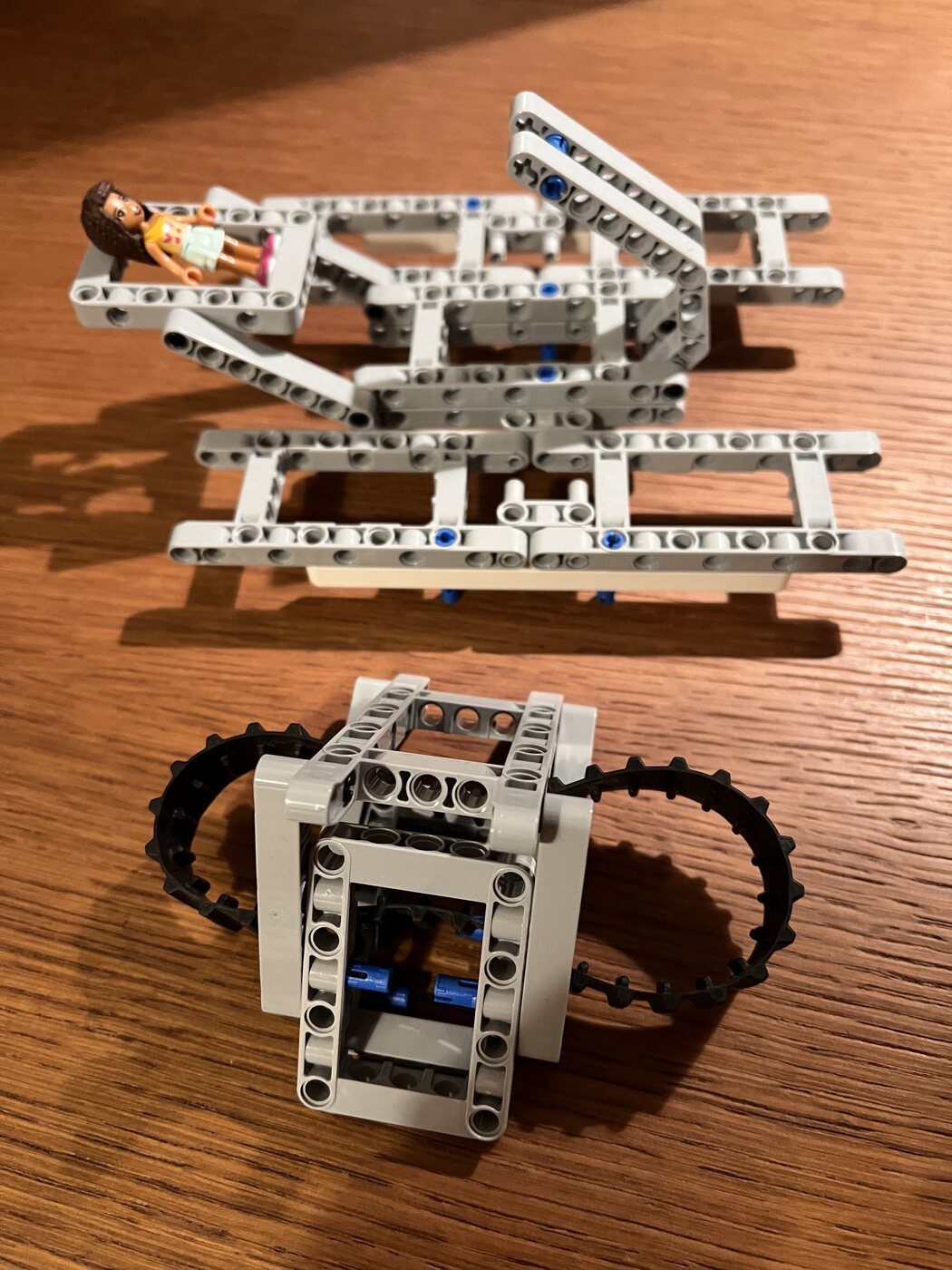
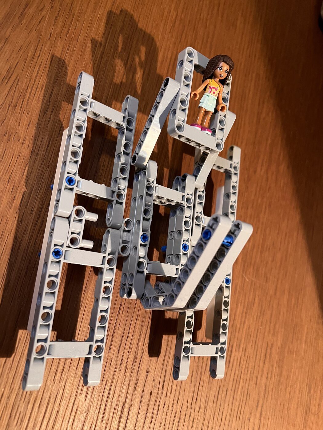
First physical model, in Lego Technic: the twin-hull frame, a track on one side and the tilting rescue pod, with a minifigure as the casualty. The pod tilts down as a ramp and lifts back up.
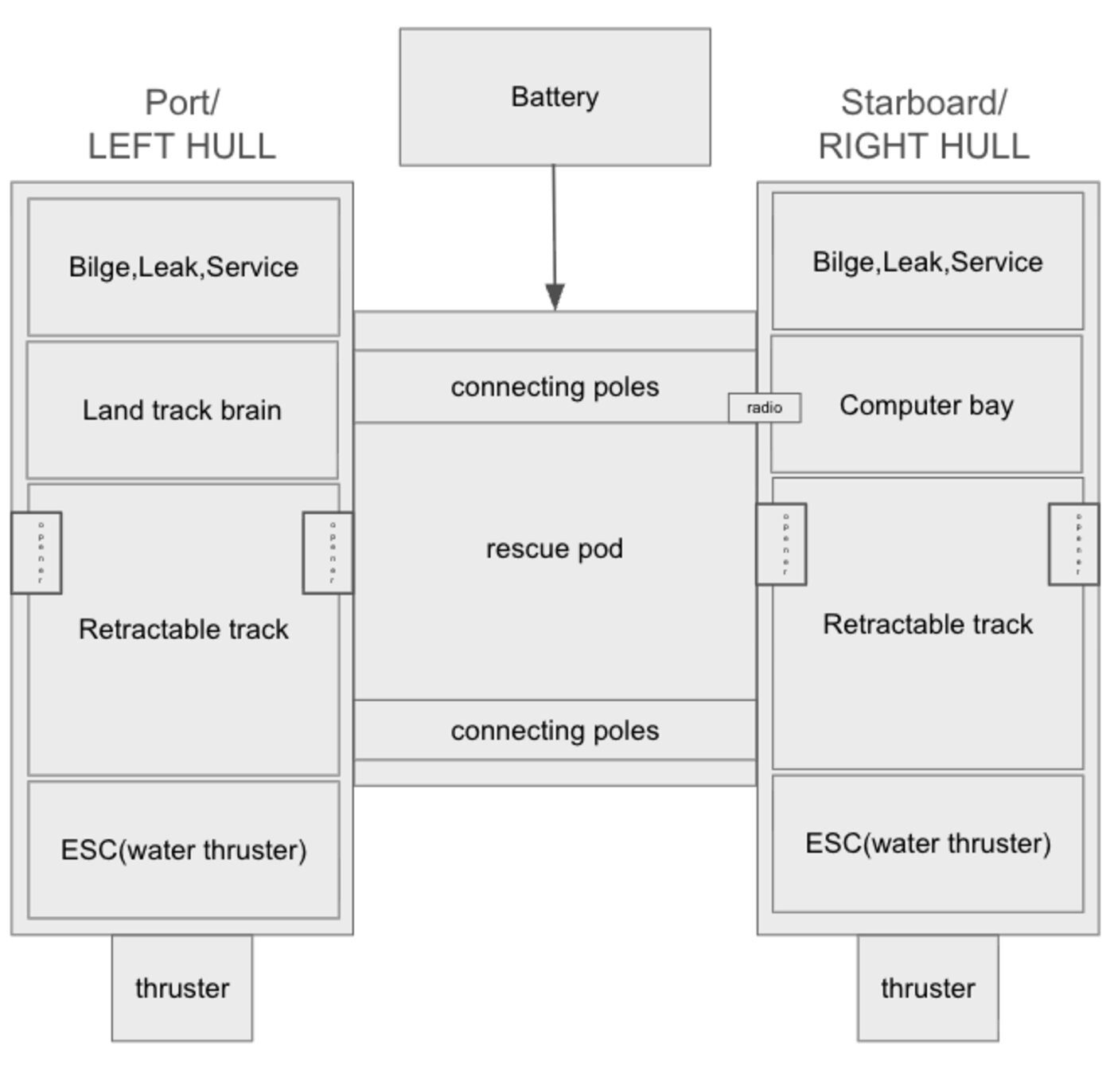
Block diagram of the full-size vehicle: bilge, leak and service modules in each hull, the land-track brain in one, the computer bay and radio in the other, retractable tracks, speed controllers and thrusters, with the battery and the rescue pod on the connecting poles.
The first version of this site, with documentation and a media gallery.
A draft poster compiled from the architecture figures and the first outcome data.
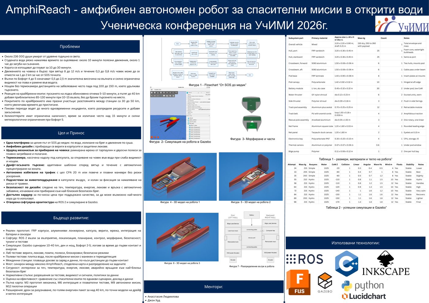
The project is presented at the 2026 student conference of UchIMI, the student institute of the Bulgarian Academy of Sciences, and receives a certificate for very good performance. The poster: the mission flow from SOS to medic, the Gazebo simulation, the Fusion model, a mass table for the full-size vessel and the first simulation runs.
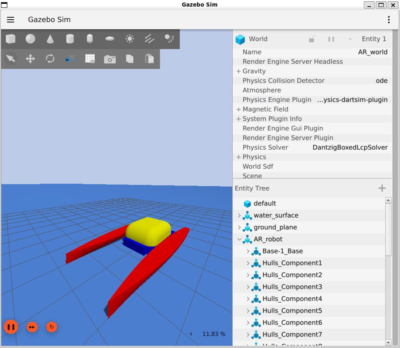
The simulation suite covers range, drift and recovery scenarios up to Beaufort 5.
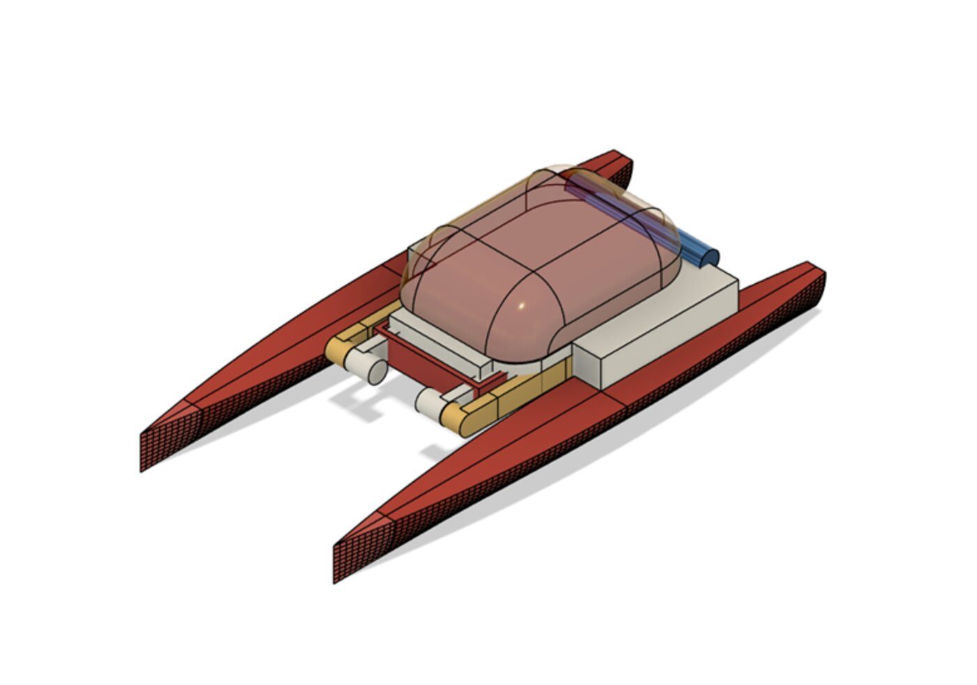
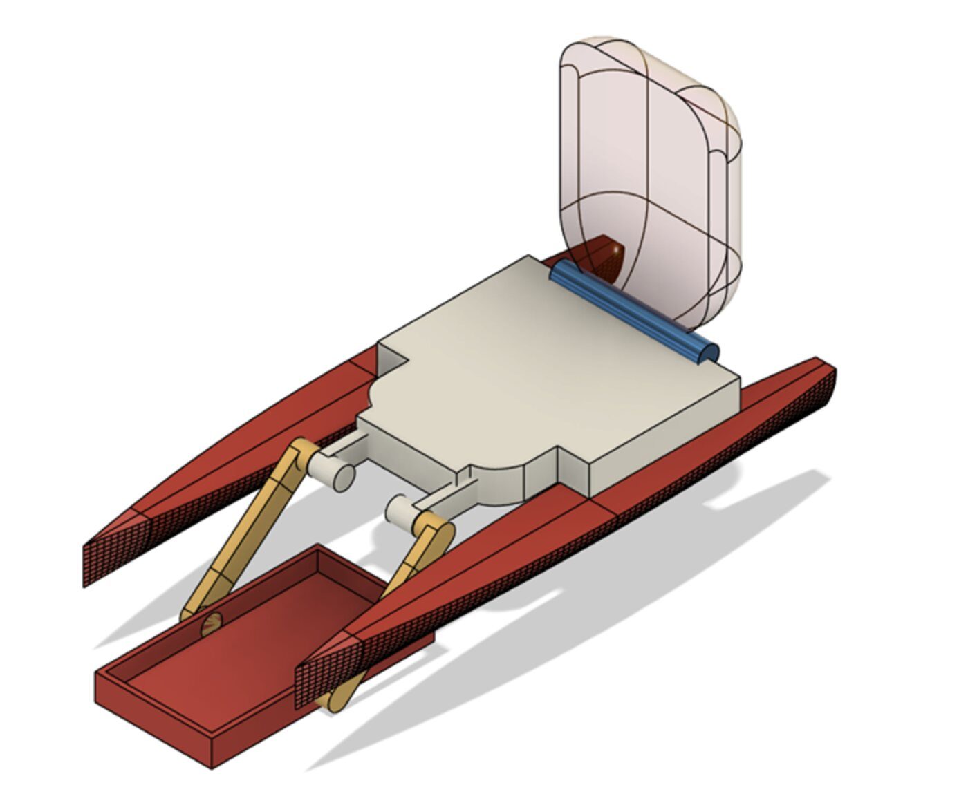
Mission requirements and the first system architecture written down. The full-size vessel modelled in Fusion 360, closed and open.
AmphiReach starts as a research project with mentor John C. Hood through Horizon Academic. The first idea on paper: twin hulls and a canopy over a rescue pod that lowers between them.